Starting a DC motor poses unique challenges. The primary issue is that DC motors require a large, potentially damaging starting current which must be limited by the starter itself. Whereas small motors can be started using a switch or contactor, large ones require a dedicated starter.
Basic operational voltage equation of a DC motor is given asV = Eb + IaRa
Where, V = Supply Voltage
Eb = Back EMF of the Motor,
Ia = Armature Current means Supply Current, and
Ra = Internal resistance of the armature.
Hence, Ia = (V - Eb) / Ra
Now, when the motor is at rest, obviously, the back EMF Eb= 0. Hence, armature current at the moment of starting can be given as Ia= V / Ra. In practical DC machines, armature resistance is basically very low, generally about 0.5 Ω. Therefore, a large current flows through the armature during starting. This current is large enough to damage the armature circuit.
A large DC motor will pick up speed rather slowly due to its large rotor inertia. Hence, building up the back EMF slowly causing the level of high starting current maintained for quite some time. This may cause severe damage. To avoid this, a suitable DC motor starter must be used for High Power Industrial Motor. Very small DC motors, however, may be started directly by connecting them to the supply with the help of a contactor or a switch. It does not result in any harm because they gather speed quickly due to small rotor inertia. In this case, the large starting current will die down quickly because of the fast rise in the back EMF. Not only can the high startup current result in potential motor circuit damage, it can also produce dangerously high torque, which can cause the rotor to literally break apart.
Possible SolutionThe problem of large starting current can be solved by adding a source of external resistance that lowers the initial current. With a source of resistance, the formula for starting current is modified to:
where, Rext = external resistance. As the motor's speed increases, Back EMF (Eb) develops and decreases the supply voltage, further dampening the armature current. As BEMF increases, the external resistance is slowly decreased until it reaches zero, which is the point of maximum BEMF. Therefore, a DC starter's primary role is to safeguard the motor's circuitry by lowering the starting current through resistance. Both automatic and manual starter are available. Most common manual starters are Three Point Starter and Four Point Starter.
All of the motor starters above are manually controlled in that the starter handle is moved by an operator.
An automatic starter operates in a similar fashion, except that automatic relays short out sections of the starter resistance either by a time sequence or when the armature current drops to a selected value. Several types of automatic starters are available. Generally all of them used Electromagnetic relay and Magnetic Contact.
You can read this tutorial to know details about the starters.
But electromechanical relays have several limitation including limited lifetime and switching speed. It also required high-current to operate and generate electromagnetic noise and interference on the power lines.
If electromechanical relay can be replaced by solid state device like MOSFET all of the above problem will be solved. But unlike electromechanical relay higher contact resistance is one of the big limitation of semiconductor device. Higher on resistance (e.g RDSon of MOSFET) may cause huge power loss for high power device like high power motor.
Electronic StartersWhile above starters are still in use, electronically controlled soft starters have been introduced more recently.
These devices are typically used to start shunt motors and feature a resistor series with parallel thyristors. When the motor starts, the high startup current flows through the entire resistor series so that resistance is maximized. A microcontroller then sends voltage pulses at preset intervals to fire the thyristors in sequence, progressively shunting the current around the resistors as BEMF develops. Like the manual starters above, the starter limits the potentially damaging startup current spike and starts the motor with "soft" acceleration.
The diagram below shows a starter similar to the device described above, except that it uses current-triggered thyristors in place of a microcontroller.
My Solution using CoolMOS
I designed an electronic starter using Infineon's 600 V CoolMOS™ C7 Gold superjunction MOSFETs. I took the advantage of low RDS(on) of CoolMOS to make my design. Without low RDS(on) this design will not be feasible because it will make huge power loss.
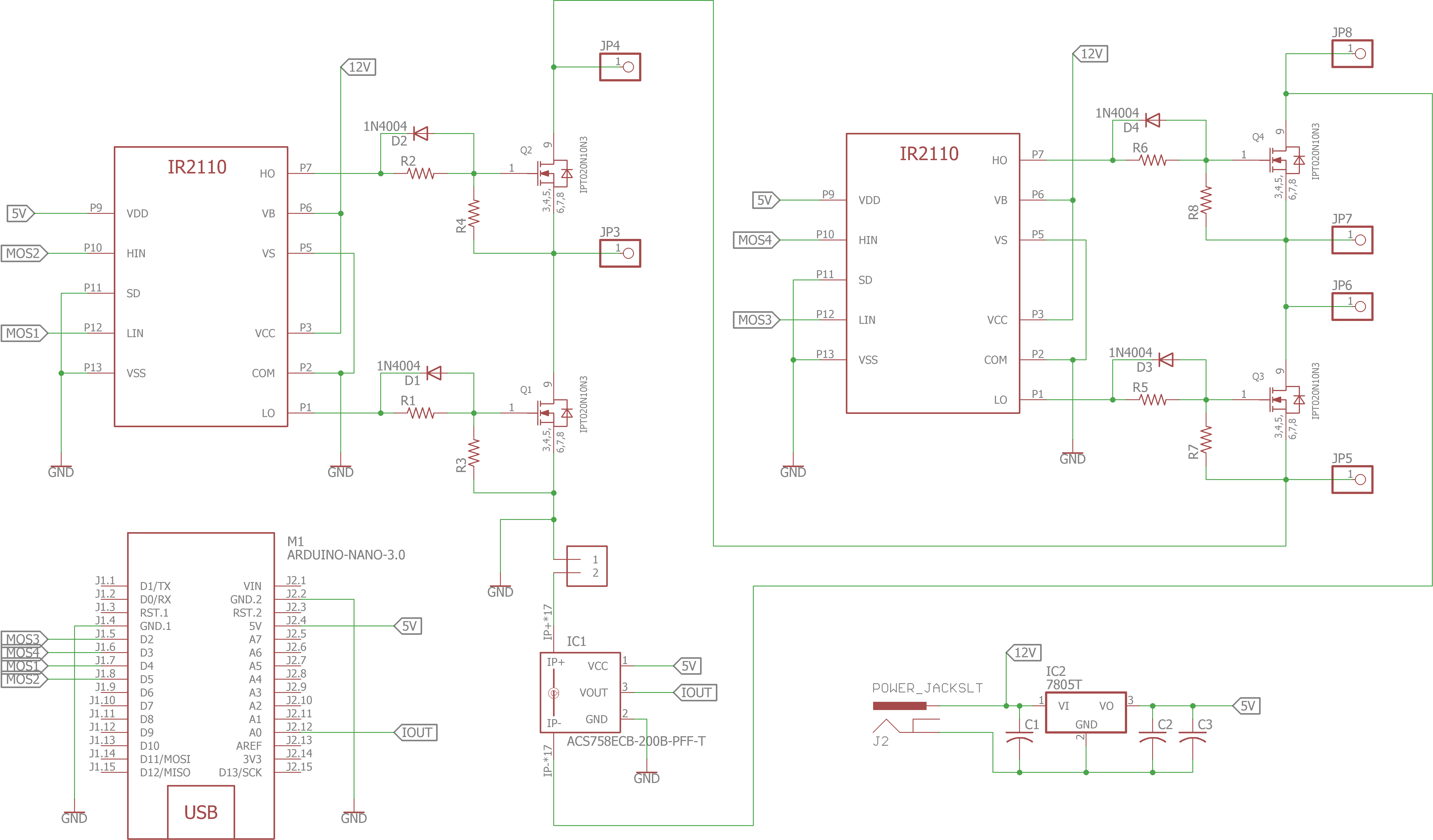
Following figures shows the topology I used for the starter. Here, three high power resistor and 4 high power switch is used. Suppose the motor required an external resistance of 150 to keep the current within safe limit at starting. Then the value of each resistance will be 50 ohm as I used three resistor in my design. When S1 is on the motor starts with 150 ohm resistance. After short period of time S2 becomes on. Resistance reduced to 100 ohm. Again after short period S3 becomes on keeping S1 and S2 on. The resistance reduced to 50 ohm. Finally S4 becomes on and the whole resistance become short circuited by the switches. The external resistance reduced to zero.
In the actual design I used Infineon's 600 V CoolMOS™ C7 Gold superjunction MOSFET for the switching. I used three 47 ohm, 50W resistor for my 500W DC motor. I took 5 seconds interval for turning the switches. I used Arduino NANO for generating appropriate pulse for the mosfets. As arduino can not drive the mosfet directly, for this reason I used IR2110 Gate Driver IC from Infineon. For overcurrent protection current sensing is required. I used ACS758 current sensor for this purpose. The current is calculated by arduino. If for any reasons current exceeds from a preset threshold the arduino turn off the mosfets automatically.
All the mosfets must turn on sequentially (Q1-Q2-Q3-Q4) otherwise the circuit can be damaged.
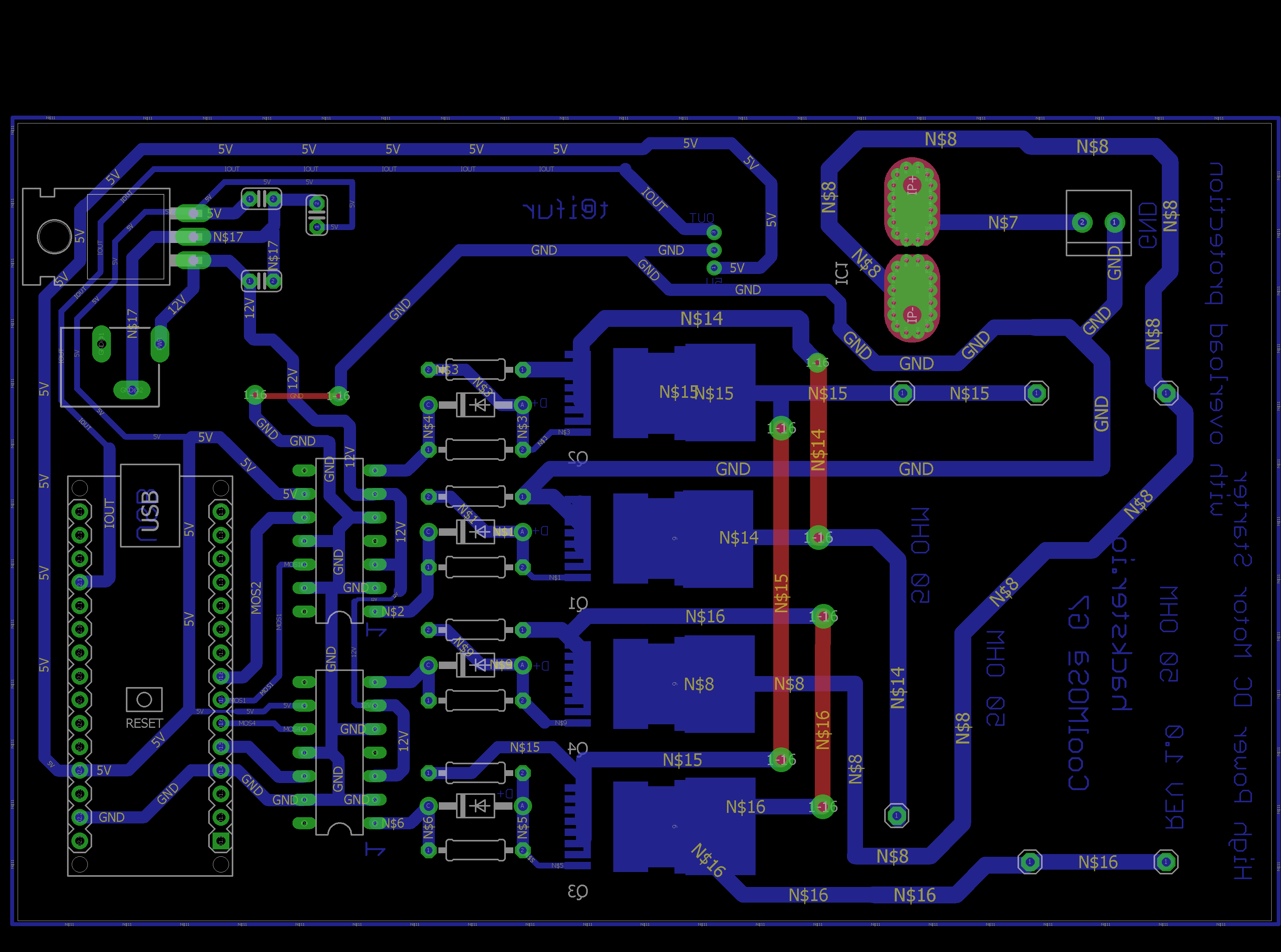
I designed the PCB layout and made a test PCB by toner transfer method.
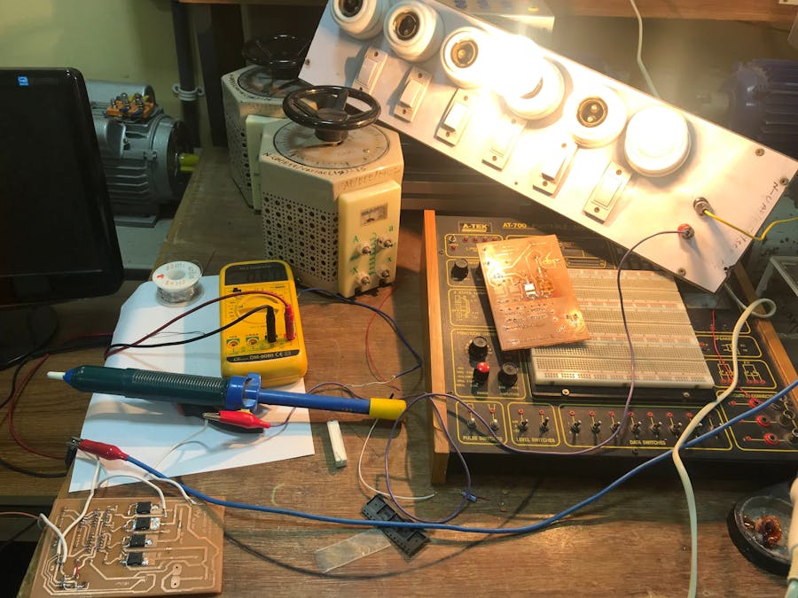
After completing the circuit I first tested the circuit using 150W lighting load. After becoming sure it perfectly working I connect a motor to test it.


Comments
Please log in or sign up to comment.