The Problem: Air and sound pollution has become a matter of great concern for us in recent years. Those who are living in cities in Asian countries have already realized how seriously air pollution has been poisoning life and degrading the environment. My motherland Bangladesh, one of the most densely-populated countries in the world, has been struggling with air and noise pollution for long. Dhaka, the country's capital, often finds its place among the most polluted cities in global indices.
The air quality of Dhaka city shows that the concentration of suspended particles in the ambient air is many times higher than normal. This air, which the city dwellers and road users regularly breathe, contains lead in concentrations reportedly almost ten times higher than the government safety standard set by the Department of Environment (DOE).
Noise pollution has also become a significant problem in Bangladesh, especially in all the divisional headquarters where sound levels are far beyond the acceptable sound level for the human ear, according to a recent study by the Department of Environment (DoE). In Dhaka, the average sound level is 80-110dB in prime areas of Dhaka city which is almost twice the maximum noise level that can be tolerated by humans – 60dB – without suffering a gradual loss of hearing, according to the World Health Organization (WHO).
My Motivationon Making the Device: Very few works have been done on air quality and noise pollution measurements and estimation in Bangladesh. There is no adequate data available for research and analysis. One of the main reason is the lack of proper monitoring device. To solve the problem I am making this open source noise and air pollution monitoring device so that any one can make a device by himself. The pollution data is also open for all. By using the smartphone app any one can get the Google Sheet of whole data from every device by email.
Features of the Project- Record sound level, air quality, temperature, humidity and location of the device.
- Sends data to Ubidots and can be visualized from Ubidots dashboard.
- Data can be monitored from mobile app and any one can get excel sheet of full data through email from the mobile app.
- The device takes power from solar. No battery replacement or charging is required.
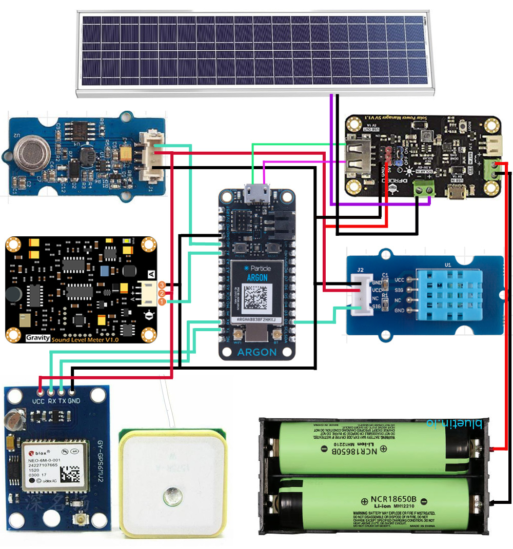
The brain of the hardware is Particle Argon board. It collects data from all the sensors and uploads the data to Particle Cloud. For measuring the sound level I used Gravity analog sound level meter from DFRobot. It can accurately measure the sound level of the surrounding environment. This product uses instrumentation circuit, low noise microphone, which makes it highly accurate and useful. It supports 3.3 to 2.6V voltage output. The decibel value is linear with the output voltage, which leads to a simple conversion, without complex algorithm. The device came with a plug-and-play jumper wire set.
As the sensor produce analog output, I connected the output of the sensor to analog pin (A1) of the Argon board.
For collecting air quality data I used Grove air quality sensor. It is also an analog sensor. So another analog connection with the Argon board is required. I choose A0 pin for this purpose.
For sensing humidity and temperature I used Grove DHT11 temperature and humidity sensor. This sensor produce digital output. So a digital connection with Argon is required for collecting the measurement data from this sensor and I selected D2 pin of Argon board for DHT11 sensor. Any digital pin will work well.
NEO-6M GPS module was used for tracking location of the device. GPS module requires UART connection with microcontroller for data communication. I connected RX pin of the GPS module to TX pin of Argon and TX pin of the GPS module to RX pin of the Argon. This is actually UART1 channel of Argon board. So you need to use Serial1 object in program sketch.
For placing of Particle Argon board in the prototype PCB board easily I soldered female pin connector to the PCB as shown in following image.
Grove sensors come with Grove cable and a Grove connector is required to connect the cable to PCB. But unfortunately, Grove connectors are not PCB friendly. So, I cut a Grove cable in the middle and soldered both parts in the PCB board. The cut out side was soldered to the PCB for connecting with Argon and other side was used to connect with Grove sensor.
The grove cable has 4 wires and one wire does not carry any signal. This is the white wire in the following image which is left unconnected.
For connecting GPS and sound level meter I soldered a pin header with the PCB. The gps module and sound sensor will be connected with the PCB through jumper wire. All ground pins are connected to PCB together with jumper wire and same is true for 5V supply pin.
The whole device will take power from solar. I used DFRobot Monocryatalline 5V 1A Solar Panel for the project. Two 2400mAh li-ion cell connected in parallel is used for storing electricity from sun. For charging li-ion battery with solar a power manager will be required. DFRobot 5V solar power manager will be the best choice for this application. This power manager module has lots of advantages. It has a built in USB port through which you can directly provide power to the Argon board through a USB cable. You can also connect the solar panel to the board directly through a USB cable. For connecting battery both JST and Green connector is available. 5V pin header is also available for providing 5V to PCB through jumper wire. From the following image you can get an overview about the the module. I became a big fan of the module!
Before placing the board to the PCB some preparation is required. I attached 4 hex spacer to the board with the screws came with the module. It also came with a heat sink and small piece of double sided silicon tape. I added it to the marked place on back side. Then I attached the board in the PCB through two extra screws after placing all the sensors.
For fixing the sensors with the PCB I used double sided tape. I cut a small piece of tape and put it on the bottom side of the air quality sensor. Then I place the sensor on the PCB at appropriate place. I repeat the procedure for DHT sensor and Sound Level sensor.
Then I placed the GPS module on the board following the same process.
Finally, I placed the battery management module on the board using screws provided with the module. I did not use double sided tape for the module because it requires some spaces on bottom to circulate air for protecting it from overheating.
I connected Argon board with the battery management module using a short USB cable for providing power to the Argon board.
I used green connector to connect battery with the battery management module. Negative terminal of the battery is directly connected to the -Ve marked terminal and positive terminal of the battery is connected to battery management unit through a SPDT switch. A plastic case for double 18650 cell is used for placing the battery. Cells are connected in parallel to increase the capacity. Cells must be in parallel. Don't connect the cells in series.
Following image shows the complete connection of all the components and sensors with the argon board. The circuit is powered up from the battery. As we have completed all the required connections for hardware in the next step we will develop the firmware for the argon board and then configure Particle cloud and web services.
We have connected all the electronics. Now it is the time of developing and writing the code for the Argon board. Particle web IDE was used for developing the program and flushing the Argon board and I found it very convenient.
Three external public libraries was used for Air quality sensor, DHT11 sensor, and GPS.
#include <Adafruit_DHT.h>
#include <Air_Quality.h>
#include "Arduino.h"
#include <TinyGPS++/TinyGPS++.h>
The code is very state forward. A separate function was made for every sensor. All functions are very easy to understand. No tricky line is included. A separate function is also made for publishing the data to Particle cloud.
void publish_data(){
       char data[256];
       char data1[256];
//I made two data array because ubidots required position value with a context, firebase doesn't
       snprintf(data, sizeof(data), "{\"position\": {\"value\":1, \"context\":{\"lat\": %.6f, \"lng\": %.6f}}, \"temp\":%.2f, \"noise\":%.2f, \"air\": {\"value\":1, \"context\":{\"quality\": \"%s\"}}, \"humid\":%.2f}",
       latitude, longitude, temperature, dbValue, air_quality, humidity);
       snprintf(data1, sizeof(data1), "{\"lat\": %.6f, \"lng\": %.6f, \"temp\":%.2f, \"noise\":%.2f, \"air\":\"%s\", \"humid\":%.2f}",
       latitude, longitude, temperature, dbValue, air_quality, humidity);
       Particle.publish("Ubidots", data, PRIVATE);  //trigger webhooks for Ubidots
       Particle.publish("Google_Sheet", data1, PRIVATE); //trigger webhook to Zapier for uploading to Google Sheet
       Particle.publish("Firebase", data1, PRIVATE);  //Store data to firebase
       Particle.publish("Firebase_put", data1, PRIVATE); //Update data to firebase.
//The main difference here is that the requestType is PUT, not POST. The PUT method doesn't create a table of values;
//it just creates a single element to hold the data, overwriting any previous data at that location.
}
Carefully note the event name for every publish method. Same event name will be used for webhook configuration for particular task. The complete code is attached in code section.
The configuration of web services is will be discuss in next section. When you finished the configuration upload the firmware and power up the device. You will observe the following result from Ubidots device tab:
If you configure any dashboard you can observe the data in graph like following image.
Air quality and GPS data are sent as Context. Air quality data context are as follows.
You will observe following output from Firebase console. This is for the PUT method configure in webhook. Without creating any row data is just update.
Following result is observed for POST request. Every time firebase receives new data it stores in a new row. This may be helpful if you like to export the data.
Zapier saves the data in Google sheet and for every receive a new row is created. You can also show the graph in the sheet.
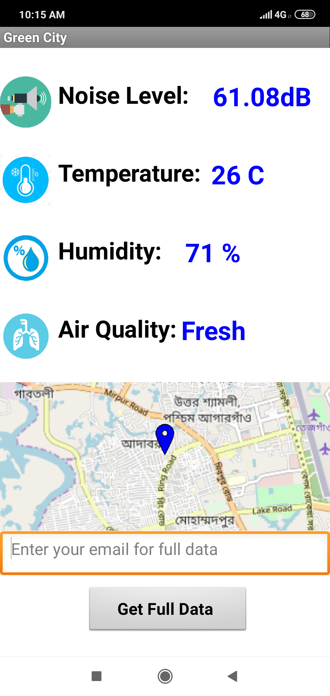
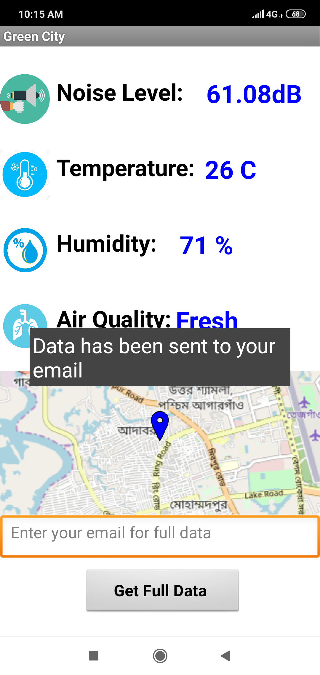
The view of the android app will be as follows.
If user send a full data request he will receive an email and the received email will be look like following:
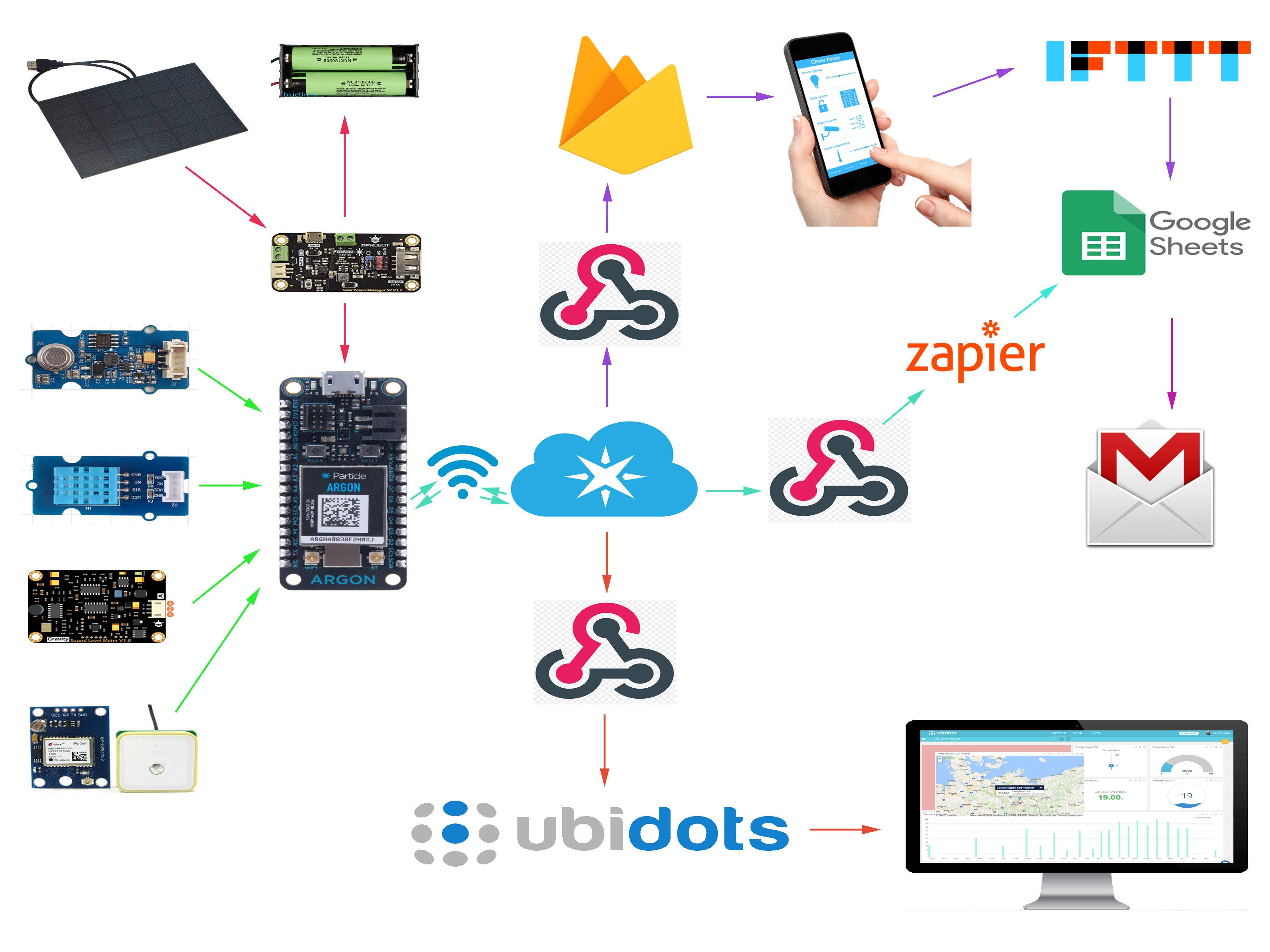
Several web services are used in the project. I used Ubidots for visualizing data, Firebase real-time database for storing the data and accessing the data through smartphone app, Zapier for making a Google Sheet using the data and IFTTT for sending the Google Sheet to user's email. All the web services are connecting to Particle cloud through Webhook.
A webhook (also called a web callback or HTTP push API) is a way for an app to provide other applications with real-time information. A webhook delivers data to other applications as it happens, meaning you get data immediately. Unlike typical APIs where you would need to poll for data very frequently in order to get it real-time. This makes webhooks much more efficient for both provider and consumer.
It is very easy to configure webhook for Particle device using Particle console. In next few steps I will show you how I configured webhook for different web services used in this project.
Configuring Particle Webhook for UbidotsTo begin your Particle - Ubidots connection, first you will need to setup your Particle device (Argon, Photon, Core, or Electron) within your particle account. Click here for simple steps to setting up your device with Particle's device platform.
You will also be required a Ubidots account. Ubidots allow free account for education and provides 5000 Credits for free.
Step 1: Create a Ubidots account from https://ubidots.com/education/ and log in to your account.
Step 2: From the right corner click on API Credentials and note the default token.
Step 3: Log in to your Particle account
Step 4: Go to your particle console and choose Integrations and click on "New Integration"
Step 5: Select "Webhook"
Step 6: Give an Event Name (1). This name must be same as the event name of Perticle.publish() method for Ubidots. I put the name as "Ubidots".
Step 7: Put your URL at URL text box. Your webhook URL for Ubidots will be as follows: (put your own token without double quote)
https://things.ubidots.com/api/v1.6/devices/{{PARTICLE_DEVICE_ID}}/?token="YOUR DEFAULT TOKEN FROM UBIDOTS CREDENTIALS"
We're going to automatically call and assign the Device ID of the Particle Device to ensure the device label in Ubidots remains unique. To do this we're going to use the pre-defined key available from Particle:{{{PARTICLE_DEVICE_ID}}} This call will automatically assign to the URL the ID of the device which triggered the webhook.
Other fields should be same as shown in figure.
Step 8: Select "ADVANCED SETTING" and complete the text editor with following text:
{{{PARTICLE_EVENT_VALUE}}}
Step 9: Click on "SAVE" and verify data is being streamed to Ubidots by login to your Ubidots.
Step 1: Log in to Firebase console console.firebase.google.com/console/login using your gmail account. Click on "Add Project".
Step 2: Give a project name and accept the terms and click to "Create Project".
Step 3: After creating project go to Database tab and select Create database.
Step 4: Choose Start in test mode and click to Next.
Step 5: From Database drop down choose Realtime Databse.
Step 6: Note the URL of the database. It will be required later on configuring Webhook from Particle console as well as making Android app.
Step 7: From the Rules tab set read and write permission as true.
Step 8: Go to Service accounts.
Step 9: Select Database secrets.
Step 10: Click on Add secret and copy it.
Step 11: Go to Particle console and from the integration start a new webhook integration. Fill up all the fields as follows. Replace URL with your own URL.
Step 12: Click on Advanced Settings, choose Custom option and paste the following json code:
{
 "temperature": "{{temp}}",
 "humidity": "{{humid}}",
 "air quality": "{{air}}",
 "sound level": "{{noise}}",
 "latitude": "{{lat}}",
 "longitude": "{{lng}}",
 "published_at": "{{PARTICLE_PUBLISHED_AT}}"
}
Sensor data will be sent to Firebase as this JSON data. It will look like following.
Finally, click on Create webhook to make it final. Webhook for Firebase is now ready.
Configuring Particle Webhook for ZapierZapier will be used to save the Particle data to a Google Sheet. Every time a new data will be published to Particle cloud, Zapier will create a new row in the Google Sheet and fill the columns with the appropriate data value. To do this we first need to make a Google Sheet in Google Drive.
Step 1: Go to your Drive and start with a Blank spreadsheet.
Step 2: First row will be the name of the data field (column). Put the name of every column according to your data. In second row just put a sample value for every data. It will help Zapier to identify the data field correctly.
Step 3: Go to https://zapier.com/ and login if you have already created an account. Otherwise create the account first. Start a new Zap. From the connect this app... dropdown choose Webhooks by Zapier and from with this one! dropdown select Google Sheets.
Step 4: Click on Make a Zap!
Step 5: Choose Catch Hook and click on Save+Continue.
Step 6: A unique webhook URL will be created for you. Copy the URL to the clipboard. Without closing the tab open a new tab form the browser and open Particle console.
Step 7: Initiate a new webhook creation from the integration tab.
Step 8: Fill up all the field. Paste the Zapier webhook URL to URL text box form the clipboard. For the Request Format select JSON.
Step 9: From the Advanced Setting select Custom option and paste the following JSON code on the text box. This JSON is same as you used for Firebase.
{
 "temperature": "{{temp}}",
 "humidity": "{{humid}}",
 "air quality": "{{air}}",
 "sound level": "{{noise}}",
 "latitude": "{{lat}}",
 "longitude": "{{lng}}",
 "published_at": "{{PARTICLE_PUBLISHED_AT}}"
}
Step 10: Click on CREATE WEBHOOK
Step 11: After creating the hook click on TEST to send a test request to Zapier.
If everything goes well you will get the following message.
Step 12: Go to the previous tab from browser and click on Ok, I did this button as you sent a test request from Particle cloud.
Step 13: Select Hook A and click on Continue to go to ACTION tab.
Step 14: Choose Google Sheets as your apps.
Step 15: From the Google Sheets Action select Create Spreadsheet Row as we like to save all value in a single sheet.
Step 16: Choose the google account for the Sheet and click on Save+Continue.
Step 17: From the Spreadsheet dropdown select the sheet you have already created for this purpose.
Step 18: Select Sheet1 for Worksheet field. You will see all the column field you created on the Sheet.
Step 19: Choose the appropriate variable for every column field from Insert a Field option. You will find all the variables from the dropdown you sent earlier as a test request from Particle cloud.
Step 20: Do the same for all fields and click on Continue.
Step 21: Click on send Test To Google Sheets to test either it is working or not.
Step 22: If everything goes well you will get a successful message.
Step 23: Open the Sheet from the Drive and you will see a new row has created. Without time all other fields are empty because we didn't sent any value on test request.
Step 24: Click on Finish
Step 25: Finally turn on the Zap.
IFTTT will be used to send the Google Sheet to the user email who like to get it. It will trigger from the Android apps.
Step 1: Login to IFTTT account and click to My Applets. Click on New Applet.
Step 2: Click on +this.
Step 3: Search for webhook and select when it appears.
Step 4: Continue with Receive a web request.
Step 5: Put an Event Name and click on Create trigger.
Step 6: Click on +that
Step 7: Choose Gmail as action service.
Step 8: Choose Send an email
Step 9: For To address field add Value 1 from Add ingredient
Step 10: Fill Subject and Body with your requirement. Paste the link of the Google Sheet for the text box Attachment URL. This file will be attached with the email.
Step 11: Click to Save to create the Applet.
In this stage we will build an Android application for monitoring data from a smartphone. A user will also be able to send a request for sending the data to his/her email.
Making app using App Inventor is very easy. No coding is required. We will read data from firebase using the app. MIT App Inventor has a built in extension for interacting with firebase. We just need to add the extension in our project.
For working with firebase you will be required your firebase URL (same URL we use in configuring webhook), the firebase token and the bucket name. Bucket name is actually the table name in firebase.
Block editor explains the interaction between different UI elements. Firebase.DataChanged method triggered for every new data uploaded to firebase. The change reflected in the app in real time.
For sending the email IFTTT maker channel is used. User will put his email address in the text box and click on send button. The following block will be triggered and IFTTT channel will receive the webhook request to send the email to the address given by the user.
Completer source code and apk file is attached in code section. You can download the source, import it to your app inventor account and modify it as your requirement.
Making EnclosureI made an enclosure of the device using plywood. Small size 5 pcs of plywood I used to make my enclosure.
I used glue and nail to make the box using the plywood pcs.
I kept a hole in top part to make it adjustable with solar panel.
Solar panel was attached on the top of the box using screws.
After fixing the solar panel with the box I placed the circuit board inside the box.
The circuit board was attached with the wall of the box using screw and hot glue. I also fixed the wifi and GPS antenna with the wall using hot glue.
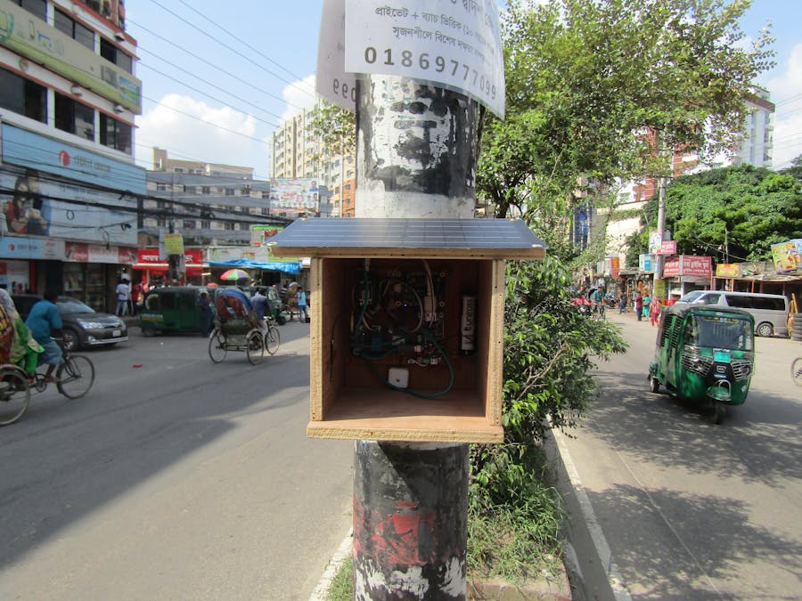
After fixing the circuit board inside the box it is ready to deploy in the field. I place the box with a light post in the middle of the road. This city road is not so busy but good to test the device.
The device is now ready to provide the data. 5W solar panel is charging the battery. This solar panel is capable to charge 2, 18650 li-ion cell in 4-5 hours. Usually it is very common to get 5-6 hours sunlight in Dhaka city.
For protecting the electronics from the environment like rain and snow a front enclosure is required. But you need to keep some place to allow air and sound inside the box. An acrylic sheet with some hole will be OK.


_zhWsCcSEcl.jpg?auto=compress%2Cformat&w=48&h=48&fit=fill&bg=ffffff)




Comments
Please log in or sign up to comment.