What do you generally do when your remote controls starts playing up?
- Do you generally use a multimeter and check the voltage and current produced by the battery?
- Or do you point the remote control to a digital camera and try to visualize the infrared light?
In this video, I am going to show you guys how to create a simple InfraRed(IR) Receiver Circuit using TSOP4838 and will also show you how to read the code send by the remote controls. You can also use this circuit as an IR remote tester.
Setup Without ArduinoLets first have a look at the setup without an Arduino.
The main component of this circuit is the Infrared Remote (IR) Receiver TSOP4838.
The TSOP4838 is tuned to 38kHz, which is typically the frequency range of the TV remote controls.
From left to right Pin-1 is the OUTput pin, Pin-2 is GND and Pin-3 is VCC. Just remember, the pin assignments can be different depending upon the TSOP variant. So, please be very careful while hooking it up to your circuit.
Now, lets have a look at the setup.
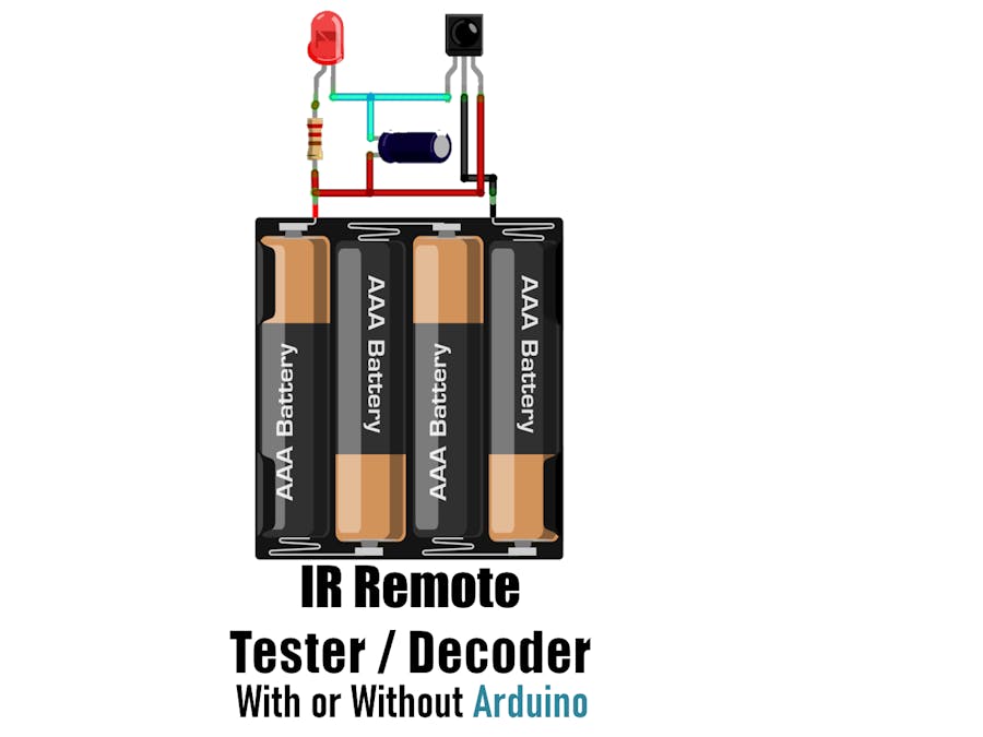
Connect Pin-2 of IR Receiver to the -ve and Pin-3 to the +ve terminal of the battery.
Then connect the -ve pin of the LED to Pin-1 of the IR Receiver and the +ve pin to the +ve terminal of the battery by placing a current limiting resistance in-between.
To reduce the flickering rate of the LED, you can add a capacitor anything between 10mfd to 100mfd between Pin-3 and VCC of the circuit.
That's it, as easy as that.
Demo Without ArduinoNow, lets do a quick test.
As you can see, when I press any button on the the remote control the LED starts flickering.
TSOP4838 demodulates the signals received from the remote control and gives the output in the form of active low to the LED.
Adding a capacitor will lower the flickering rate of the LED.
The supply voltage has to be strictly between 5V-6V.
Setup Using ArduinoNow, lets set this up using a MicroController and try to read the demodulated signals.
Connect the +ve pin of the IR Receiver to 5V, -ve to GND and the OUT pin to Pin-2 of the Arduino.
You can also add the optional LED to this setup to get a visual effect when the Receiver decodes the signal.
Now, go ahead and launch Arduino IDE and go to "Tools" > "Manage Libraries".
Download and Install the latest release of the "IRremote" library from the library manager.
Then, go to "Examples" and open the "SimpleReceiver" example. Go ahead and load the code without making any modification to the Arduino Board.
Demo Using ArduinoFor this demo, I am using a Panasonic and a Sony remote control. The decoded data will be shown using the Arduino IDE's Serial Monitor.
As you can see when I press a button on the remote control, the LED lights up and the decoded data is displayed on the serial monitor.
The serial monitor displays a lot of information, but the one of my interest is the "Source" and the "Command" send by the remote control.
UsesSome common uses of this project includes:
Controlling devices using a remote control
Decoding data sent over IR
Troubleshooting remote controls
Lighting up LED strips near your TV whenever you press a button on the remote control
ThanksThanks again for checking my post. I hope it helps you.
If you want to support me subscribe to my YouTube Channel: https://www.youtube.com/user/tarantula3
Video: Video Link
Full Blog Post: Blog Post
Datasheet: Download
Support My Work:
BTC: 15cNh9hup8jidCVPwa1DTcxeoh2FPijVrX
LTC: LbquH9Ku78vHtcm3LZnWXpD1JQWdKzeV4v
DOGE: DEB2QBAihnBRhGsaB8P7kz559TDiucQhX6
ETH: 0x5d8c9ba0e54d8354d4af81871db26daa190d2194
BAT: 0x939aa4e13ecb4b46663c8017986abc0d204cde60
LBC: bZ8ANEJFsd2MNFfpoxBhtFNPboh7PmD7M2
COS: bnb136ns6lfw4zs5hg4n85vdthaad7hq5m4gtkgf23 Memo: 572187879
BNB: 0x5d8c9ba0e54d8354d4af81871db26daa190d2194
Thanks, ca again in my next tutorial.


_ztBMuBhMHo.jpg?auto=compress%2Cformat&w=48&h=48&fit=fill&bg=ffffff)


Comments
Please log in or sign up to comment.