The Blind Man Who Invented Cruise Control.
Cruise control system is a fabulous invention that helps us avoid speeding tickets and gives our feet a break on long drives. In spite of the fact that almost all drivers have used cruise control at some point, only a few drivers know much about the features origins or about the man who invented it. Ralph Teetor invented the cruise system for modern motor vehicles… and he was blind.
As early as the late 1700s, engineers began using cruise control-type technology to regulate steam engines. Ralph Teetor was personally inspired to make cruise control for cars after a few too many frustrating drives with his lawyer, who had a nasty habit of speeding up and slowing down too often. He developed cruise control in the 1940s and patented it in the early Nineteen Fifties.
Some advantages of cruise control :
- · It's useful for long drives.
- · Some drivers use it to avoid subconsciously violating speed limits.
- · Increased fuel efficiency.
The purpose of this project is to have a simplest speed control unit done by digital controller and here we used Arduino Uno development board to apply a basic control theory to the system. PID loop is used in this project to control the speed of DC motor. And we also included different controller types to control the speed of DC motor. GUI is made for setting the required speed and serial plotter & monitor for better visualization the data form the motor.
Aim and ObjectivesThe aim of the project includes for several reasons:
- Control the speed of motor by applying different controller types (pid, pi, p, i) and learn the difference between them.
- For more understanding the control theory and tuning methods.
- Autocad skills ( 2D & 3D parts )
- Arduino c programming ( program arduino uno )
- Matlab & Simulink ( T.f & parameter estimation & tuning PID )
- C# programming ( build GUI )
- kalman filter algorithm ( filter the speed sensor from noise)
- Non-linearleast squares algorithm ( parameter estimation)
The physical parameters for the DC motor “MY6812” are: ( from parameter estimation)
- (J) moment of inertia of therotor 1.2130e-05 kg.m^2
- (b) motor viscous frictionconstant 1.5319e-04 N.m.s
- (Ke) electromotive forceconstant 0.0034 V/rad/sec
- (Kt) motor torque constant 0.0034 N.m/Amp
- (R) electric resistance 0.0710 Ohm
- (L) electric inductance 0.0127 H
1.Transfer Function.
2.State-Space.
the armature voltage is treated as the input and the rotational speed is chosen as the output.
3.Simulink Modeling.
4.PID control.
The speed of the dc motor can be controlled using a different controller. In this project,speed is controlled by the PID controller.
A PID controller produces an output signal consisting of three terms- one proportional to error signal, another one proportional to integral of error signal and third one proportional to the derivative of the error signal.
- The proportional controller stabilizes the gain but produces a steady state error.
- The integral controller reduces or eliminates the steady state error.
- The derivative controller reduces the rate of change of error.
PIDcontrollers have higher stability , no offset and reduced overshoot .
5.Tuning PID
There are many different ways to tune PID control of any system like ZIEGLER NICHOLS methods or even TRY AND ERROR method to get the required performance.
In this section, PID tuner toolbox is used to tune PID depends on response time [slower– faster] and the transient behavior [aggressive – robust] that you give.
6.Parameters Estimation.
Parameter estimation plays a criticalrole in accurately describing system behavior through mathematical models suchas statistical probability distribution functions, parametric dynamic models.
Common tasks for parameter estimation:
- Importing and analysis input-output data, like the applied voltage as input and rotor speed as the output of a DC motor.
- Determine which model parameters and initial conditions to estimate, such as motor inductance and friction, and other parameters.
Non-linearleast squares method is used to estimate the unknown parameters.
It compares between two data:
- measured data
- simulation data.
Measured data comes from real system while simulation data comes from mathematical model with initial assumption as shown below :
J=0.01;
B=0.1;
K=0.01;
R=1;
L=0.5;
And after a number of iteration, the simulation data try to follow the measured data by changing these parameters to match measured data and give us realistic model result.
For displaying results by PC a GUI is designed by a c sharp windows form application using visual studio2015 text editor. by the designed GUI the power, voltage, current draws by the motor will be displayed in this application. Also, the desired speed and the value of speed sensor & error & output PWM will be shown.
Login Form.
When opening the application, a login form will be shown and you have to enter the user name and password.
- · User name: user
- · Password: 1234
Control Unit Panel.
- · Setpoint : desired speed that user need.
- · Sampletime : default 20 milli seconds.
- · Disturbance: [0 -500 ], effect the value of speed sensor.
- · Setmode : either “auto” or “manual”, where “manual” turn off the PID algorithm.
- · Open loop configuration : activate open loop instead of closed loop [0 – 255], where “0” turn off the motor while “255” max speed can handle.
- · Controltype : “PID”, “PI “, “P”, “I “.
Open the connect button for making a connection between ARDUINO and the PC.
- · Com ports: choose what available.
- · Baud rate: 9600
Then press open button from port control panel.
The GUI have also both serial monitor and serial plotter for better visualization data incoming from ARDUINO.
For serial monitor, you can copy the data and analysis it by either Microsoft excel or Matlab.
you can also save the data as txt or csv.
- 1.How to filter the reading of speed sensor: Using kalman filter algorithm, Excellent filtering but it delay the signal a little bit.
- 2.How to estimate the parameters of the motor: Using non-linear least squares method.Good estimate but it have some error.
- 3.How to send and receive command from a computer :Make a GUI using c sharp windows form application.
- 4.How to build mathematical model of the motor:Using Simulink and create subsystem.
- 5.How to tune PID control: Using system identification toolbox from Matlab Very good result.
- Cruise control system in cars.
- to regulate flow, temperature, pressure, level, etc.
you can improve the system by doing the following : [@version2]
- · Implement PID loop on faster microcontroller.
- · Instead of using Bluetooth to make a connection between the interface and Arduino, a Wi-Fi model is better to change the speed and monitor the system from any place of the world.
- · Add features that make the application automatically calculate the rise time and overshoot also settling time.
- · Auto tuning option.
- · Total days working : almost 120 days.
- · Total month working : 120 / 30 = 4 month .
- · Almost[2-6] hours per day.
Power Supply.
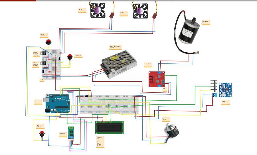
Power supply is needed for powering ARDUINO UNO and for motor.
- Power = 300 watt .
- DC output = 12 volt - 5A .
- DC output = 24 volt - 10A.
Arduino Uno.
Either arduino uno or any digital controller to implement PID loop and for control the speed of motor and sending or receiving data by serial communication Bluetooth.
- · Microcontroller board based on the ATmega328P.
- · It has 14 digital input/output pins.
- · 6 analog inputs.
- · 16 MHz.
- · Arduino C/C++ .
Encoder600ppr Incremental.
A rotary encoder is used to measure the rotational speed, Angle and acceleration of the object and the length measurement. Suitable for intelligent control of various displacement measurement.
- · 600 pulses per revolution ( 600 ppr).
- · Power= 5 -24 volt DC .
- · Output = 2 phase [A & B] output rectangular .
- · Maximum mechanical speed: 5000 R / min .
2D part& 3D part .
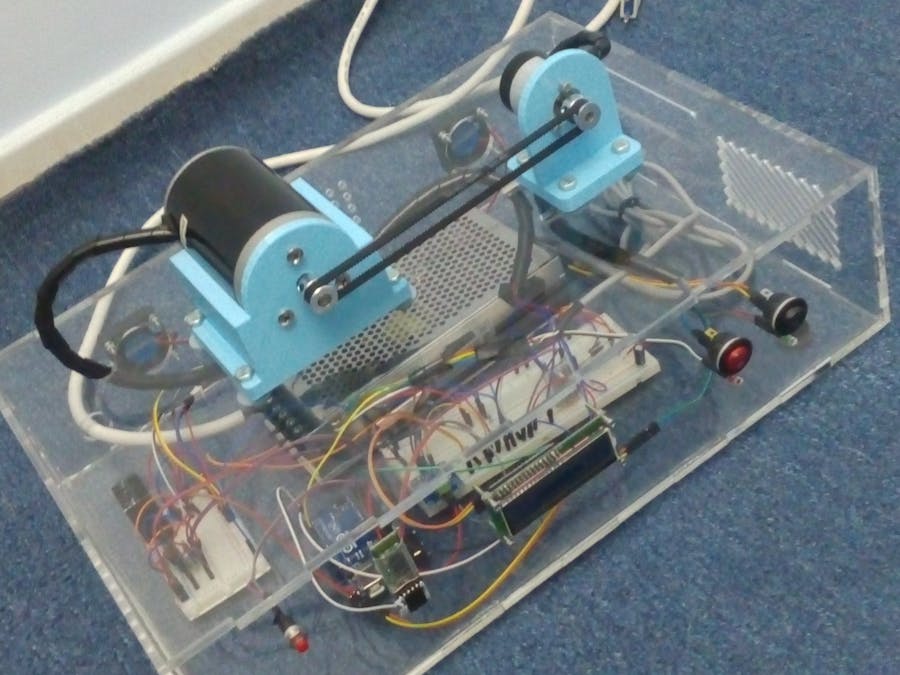
2Dpart is done by CNC machine for enclosure box to safety operation and not get hurt from power source AC Current. while 3D part is done by 3D printer for holder bracket of the DC motor and encoder speed sensor.
- · Software design : AutoCAD.
- · 2D part final product : CNC machine .
- · 3D part final product : 3D printer .
DC Motor.
MY6812 24V /150W high speed brush motor is used in this project. It Popular as a scooter motor or general application motor.Extremely durable and reliable.
- · Power output = 24V/150W.
- · Current without load : < 0.9 A .
- · Rated current ( with full load ) : < 8.5A .
- · Max speed (rpm) : 3500 +/- 5 %.
- · Rated speed (rpm) : 2500 +/- 5 %.
- · Rated torque : 0.56 Nm .
- · Shaft diameter : 8 mm .
- . Efficiency : > 68%.
Mechanical Parts .
Consist of two GT2 pulley[pitch =2mm ] and a closed loop belt .
- · GT2 pulley 20 teeth [6mm] bore 6mm wide.[encoder]
- · GT2 pulley 20 teeth [8mm] bore 6mm wide.[motor]
- · Gt2 closed loop belt 400mm length 6mm wide .
LCD with I2C.
LCD 16X2 with I-squared-C synchronous communication is used in this project to display the values of set point & actual speed& error & PWM output.
With I2C device you can control the LCD with only 2 pin from any microcontroller. they are the SCL (serial clock pin ) & SDA (serial data pin) .
On arduino uno :
- A4 (SDA) .
- A5(SCL).
- · LCD (Liquid Crystal Display).
- · Power = 5v .
- · They are good for displaying information like sensors data.
- · They are very cheap.
Motor Driver.
A motor driver is a circuit which is usually used to control motors in autonomous robots. Motor driver act as an interface between Arduino uno microcontroller and the motor.
- · IRF540 Power MOSFET .
- · 10 k ohm pull-down resistor from gate to source .
- · 1N5408 freewheeling diodes.
Bluetooth HC-05 .
This module is used to communicate between Arduino uno and any device with Bluetooth functionality like a Phone or Laptop .
- · Operating Voltage: +5V .
- · Range: < 100m.
INA219 Power Monitor Sensor.
To measure the current draw of the DC motor and also to measure the voltage bus & power.
- · This module can be sensed bus voltage range 0 V to 26V.
- · 12-bit resolution.
- · Measure high side voltage and DC current draw.
The goal was to design, build, and program a speed control unit to be used for testing the theory behind control system . and these are the advantages :
- · Learn about the control theory and the controller tuning methods.
- · Learn how to design a GUI that communicate with Arduino and how to send data to-from Arduino by serial communication.
- · Learn about different methods of filtering a signal that content a noise with it like Kalman filter algorithm.
- · Learn about the basic idea of cruising car system.
- · Have the opportunity to learn a number of different software like Arduino ide, c sharp, AutoCAD 2d&3d, excel, Matlab &Simulink, etc.


_ztBMuBhMHo.jpg?auto=compress%2Cformat&w=48&h=48&fit=fill&bg=ffffff)


Comments
Please log in or sign up to comment.