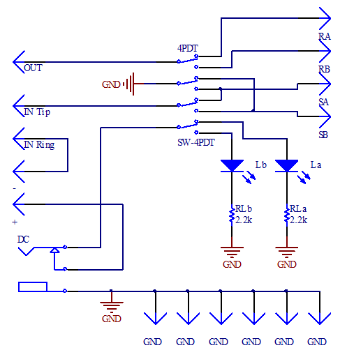
The Dual Loop allows you to alternate between two different effects loops. It provides two switchable loops (send / return) with a single foot switch. Steps
Categories
Tayda Electronics Kits, DIY Projects, DIY Guitar Effects
Dual Looper Step 1 of 5The Dual Loop allows you to alternate between two different effects loops. It provides two switchable loops (send / return) with a single foot switch.
Products
Dual Looper DIY PCB Guitar Effect
3.3K OHM 1/4W 1% Metal Film Resistor
4PDT Stomp Foot / Pedal Switch Latching
DC Power Jack 2.1mm Barrel-Type PCB Mount
PCB DESIGNATORS
You can choose any type and color of diode led. The resistors set the brightness, recommended values for a normal led are from 2.2k to 4.7k Ohm. For high bright leds, you should use higher values for the resistor, from 10k to 22k Ohm.
Board
Resistors
RLa - 3.3K OHM 1/4W 1% METAL FILM RESISTOR
RLb - 3.3K OHM 1/4W 1% METAL FILM RESISTOR
Leds
La - LED 3MM GREEN
Lb - LED 3MM GREEN
Switch - 4PDT STOMP FOOT / PEDAL SWITCH LATCHING
Connector - DC POWER JACK 2.1MM BARREL-TYPE PCB MOUNT
Schematics Step 2 of 5PCB DESIGNATORS
You can choose any type and color of diode led. The resistors set the brightness, recommended values for a normal led are from 2.2k to 4.7k Ohm. For high bright leds, you should use higher values for the resistor, from 10k to 22k Ohm.
PCB BACK
Resistors
The resistors are ¼ Watt metal type. You can either use a multimeter or the color bands to obtain their values. Resistors don’t have polarity; you can assemble them in any direction.
Led diodes
Led diodes have polarity, the cathode is indicated as a flat surface on the side of the diode and also it is the shorter led. On the PCB, the cathode is marked as a flat side and anode as a round side.
See our generic soldering instructions page.
You should use a 15-30W soldering iron and 1 mm of diameter 60/40 (60% tin, 40% lead) solder. The solder will release fumes that are harmful to your eyes and lungs, work always in a well-ventilated environment and avoid breathing the smoke created.
Warm up the iron and clean it with a humid sponge before soldering. Place the component and firmly hold the PCB on the table or holder. Heat the pad and the lead for one second by touching them at the same time. Then, feed around 1-3 mm of solder and make sure it flows properly. If the solder has not been applied correctly you can create a bad connection (cold solder joint). A good connection should cover the path and lead without touching any other pad. Finally, cut the lead with a cutter and inspect the joint by visual or by using a multimeter.
Enclosure and wiring Step 5 of 5You can create your own element distribution and use many types of enclosures. It is recommended to use a metal enclosure and connect it to the ground in order to attenuate the noise. For this project, for example, you can use the 1590B, 125B or 1590BB enclosures available at http://www.taydaelectronics.com/hardware/enclosures.html . After the drilling, you can paint and decorate the enclosure as you desire. Finally, install all the elements and you can begin with the wiring.
You can place the leds directly to the PCB or wire them. If you want to use the 1590B enclosure, you can place the DC jack directly on the PCB. You can also use other type of DC jack and wire it.
PLACEMENT
You can create your own element distribution and use many types of enclosures. It is recommended to use a metal enclosure and connect it to the ground in order to attenuate the noise. For this project, for example, you can use the 1590B, 125B or 1590BB enclosures. After the drilling, you can paint and decorate the enclosure as you desire. Finally, install all the elements and you can beguin with the wiring.
You can place the leds directly no the PCB or wire them. If you want to use the 1590B enclosure, you can place the DC jack directly on the PCB. You can also use other type of DC jack and wire it.
DC POWER JACK 2.1MM ENCLOSED FRAME WITH SWITCH or DC POWER JACK 2.1MM BARREL-TYPE PCB MOUNT
In the following figures you can find some examples of layout for 1590B and 1590BB enclosures.
WIRING
For the wiring you should use 24 AWG stranded wire. Wire all the elements as indicated in the following diagram (with bottom view of the PCB), for the ground (GND) no mater the order you use if all the elements are connected. You can power up the circuit with DC adapter (9V) or a battery. The diagram shows the connections to use the DC connector as negative tip (standardized 2.1 mm with a negative tip orientation).
Dual Looper DIY PCB Guitar Effect
3.3K OHM 1/4W 1% Metal Film Resistor


Comments
Please log in or sign up to comment.