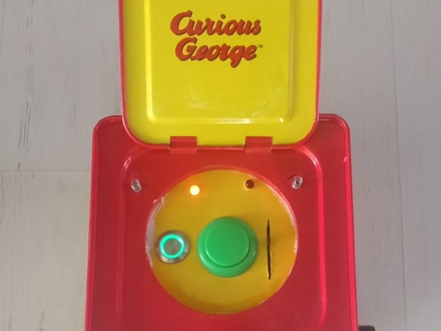
This project was created due to our Physical Computing Class. The theme was Children's Toy for toddlers and we wanted to create something with a Jack-In-Box (JITB). It was definitely a learning process but totally achievable and with our instructions, you can have your very own!
Step 1The first thing you will need is a Jack-In-The-Box. We ordered the Curious George one off of Amazon: link here --> https://www.amazon.com/Schylling-CJB-Curious-George-Jack/dp/B00004NKLB/ref=sr_1_2?ie=UTF8&qid=1517171755&sr=8-2&keywords=jack+in+the+box
The next thing we did was cut the bottom of the JITB off with a Dremel using a circular saw blade for metal. After carefully sawing it off, we filed down the sharp edges with a metal file. If you are under 18, have an experienced adult supervise and always use eye protection.
After the bottom is detached, remove the sock monkey and spring. The next step is to remove the music box to make space for the servo motor. The only way to remove the music box is to cut and pull off the two metal strips holding everything in place. We used a metal cutting clipper and it worked perfectly, we believe the box is Tin so any metal clipper harder than Tin should work. Also use a Philip's Head screw driver to remove the flat black musical plate.
After you have the music box out, it time for the servo that will unlatch the top via Arduino. What we did was wedge the servo where the music box was in between two pieces of balsa wood and used electric tape to keep it in place. It takes some testing to set the angle of the motor to the right place to open to the box because you do not the white piece to go over the red latching mechanism.
The next step is the interactive electronics. In order to mount them to the center, we cut and traced out a thin piece of wood. Using a circular blade on a Dremel for the slide pot hole, a wood bit for the larger holes, and a drill for the led holes.
The next step is to cutting the wires for the electronics, pre-tinning them with a soldering iron, and soldering them onto the electronics. There are two wires per LED, four for the encoder, two for the latching button, one for the green button, and one for the slide pot. Look at the diagram to measure out sizes for each.
The seventh step is attaching the electronics to the wood. The two buttons had nuts that came with them to tighten them onto the wood but the slide pot and LEDs had to be hot glued. Before we attached them, we cut out a piece of yellow construction paper and cut out the holes to cover the wood (using a glue stick to attach to the wood).
Because the JITB no longer has a bottom, we used velcro to attach a thin wooden plate to it where the 9v Battery and breadboard will go.
The next step is expanding the hole where the crank was to fit the rotary encoder. Use the DeWalt Drill to expand the hole and file down the edges with a metal file. Also, upload code onto Arduino.
The last step is assembly. Use a strong super glue to attach the wood (with interactives) to the circle by applying it around the circle and pressing the wood onto the circle. We used Gorilla Heavy Duty Construction Adhesive and let it cure for more than 24 hours. Also, because you do not have the spring inside a sock money, take apart two pens and trim the springs inside the pen before gluing it towards the back of the lid on the sides of the circles. The breadboard was attached with electric tape and the encoder also had a nut on it. After everything is in place, plug everything as in the tinkerCAD diagram and close bottom with velcro.


_3u05Tpwasz.png?auto=compress%2Cformat&w=40&h=40&fit=fillmax&bg=fff&dpr=2)
Comments
Please log in or sign up to comment.