Created by: Rachel Wang (raw8), Michael Tang (mjt6), Jaejun Ku (jk75), Alex Berlaga (awb4), Ryan Draper (rmd10), Kelly Huang (kh57), Mark Pepperl (mrp11), Pete Sirithanachai (ps65)
Project Overview and MotivationsWelcome to Rainbow Vibe Lights, inspired by the iconic Memorial Hermann, or, better known as “The Rainbow Building.” Situated next to Lovett College, The Rainbow Building presents a spectacular light show that beams across Houston like a brilliant North Star, guiding generations of Rice students to Lovett College. As freshmen from Lovett, we distinctly remember advisors telling us at O-Week, “When you see The Rainbow Building, you’ll know you're home.”
For anyone who misses the distinctive ambience of The Rainbow Building, whose changing rainbow colors symbolize the diversity and brilliance of Rice, we wanted to create fading RGB LED lights with a tilt switch that combines what Rice students love the most: unconventional wisdom and, of course, Rice University. As a result, our engineering startup designed this product for the community to enjoy, whether that community is Lovett College, Rice University, or Houston, Texas. We hope that whatever you may be doing in quarantine, and wherever you may be in the world, you’ll turn on Rainbow Vibe Lights and feel at home.
Essentially, our project fades between different colors using Pulse Width Modulation. This generates a beautiful fade and ombre of lights for all your ~vibe~ purposes. The tilt switch allows you to change the frequency of the fading lights, so you can change them accordingly to the vibe of your party, gathering, or quarantine. And lastly, if you really like a color and would like to pause it, you can hold down on the button and keep the color. As another reminder, here is what you need before getting started!
Hardware Required:
* Tiva C Series TM4C123G
* Breadboard
* RGB LED
* 12x Jumper Wires
*Tilt Switch
*2x 1k Ohm Resistor
*Push Button
This is so cool! Teach me how to make this!
How to Build OverviewHow do these lights work? Here's a quick overview! We build a circuit on our breadboard, connecting the LED to ports on our microprocessor. We configure three pins depending on their properties; it may not matter which exact pin we choose, but the pins must have analogWrite() capabilities. The fourth pin must connect to a voltage source. Then, we add a tilt switch, and connect this to our microprocessor for a voltage source and a pin that has digitalRead() capabilities.
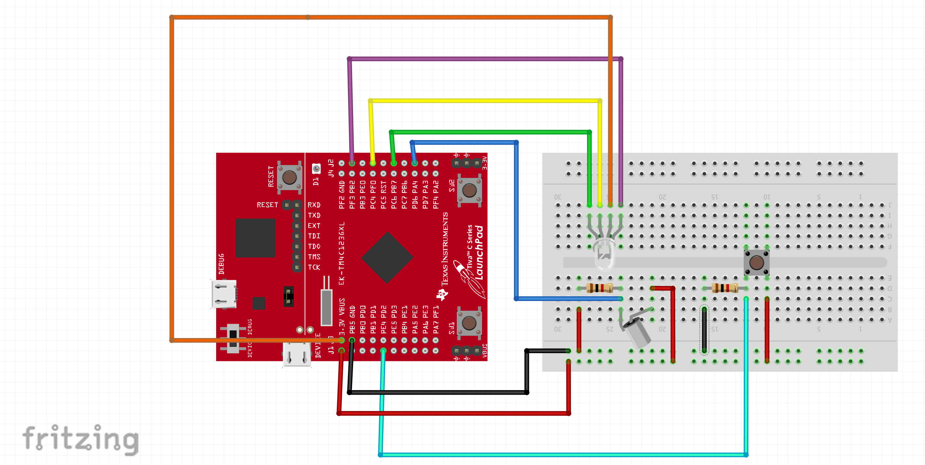
Hardware Components1. As guidance, we used this diagram from Energia. Note that for our Launchpad, we must choose different ports, but the setup on the breadboard is similar.
2. Then, refer to this diagram for which pins to connect your wires from the breadboard to. We want the pins to have analogWrite() capabilities. You can choose any pins that you would like! For the voltage, you can connect to VBUS.
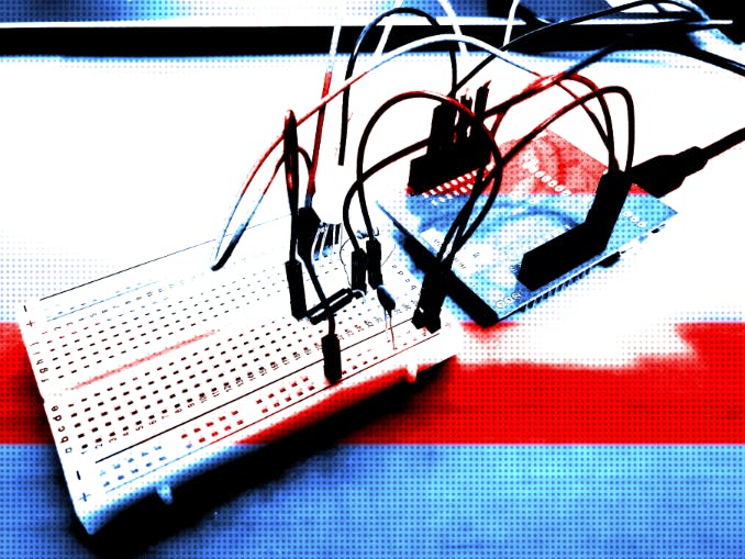
Here is an example of what we did:
3. Now, we will add the tilt switch. Make sure you do not put this on the same row as your LED. On one side of your switch, you should connect a wire to the 3.3V port, because we will change the frequency of the lights by seeing if there is current going through the tilt switch or not. The other wire should connect to a pin (use the diagram we provided!) that has digitalRead() capabilities. Then, we add a 1k Ohm Resistor to prevent a short circuit and a wire to GND to properly ground our circuit. In fact, grounding the circuit is one of the most critical parts of the design! Without it, when you tilt the switch the LED just gets stuck on red. We suspect that this may be due to AC noise caused by the large pulse between 3.3V to 0V interfering with our LED, although we are not completely sure.
4. Finally, sometimes when you have mood light and want to vibe, the flashing light can become a bit distracting. Hence, we decided to add functionality so let our client pause the light at will, for moments where they wanted to space out to a particular color. We did this by adding a push button. The push button is fairly simple; just connect it somewhere on the breadboard, connect one end to power (3.3V), the other end to a pin with digital read (look at the schematic!!). Then, when you press on it, the light will pause at whatever color you are at. You can see this below.
Notice that just like with the tilt switch, we also grounded the push button. Now, the light works perfectly fine if you don't ground it -- that is, with one catch. When we didn't ground it, we found that when turning "on" the tilt switch to the higher frequency setting, the light wasn't flashing quite as fast as it was supposed to (perhaps about a 2ms delay, when we had in reality set it to a 1ms delay). Once again, we suspect this may be due to AC noise, although we're not completely certain.
And with that, we're done with the hardware component! if you'd like to see this more clearly in a schematic, you can find that at the bottom of this page right about the code.
Software OSA template can also be found on Energia's website! Here is a glimpse of our specific code.
1. setup(): Make sure you define your pins according to what you have chosen! This part may require editing. You can also customize the delayTime to be whatever you choose. This determines your frequency!
Essentially, we are just setting up by defining our pins and flashing red, blue, and green.
2. loop(): Because the tilt switch allows the user to change frequency, we must have an if-else statement, which allows us to change the frequency of the fading lights depending on the voltage (LOW or HIGH, as we have previously set up). This is where the digitalRead() capabilities become helpful! You can use the same code for fading, but change the delay time. We've given below just a small tidbit of how exactly we implemented the functionality between the tilt switch and frequency: you can see the full code we used at the bottom of this page! One of the biggest problems we ran into here was trying to figure out how exactly to make sure our program could tell if our switch was flipped if we were already inside either the "if" or "else" portion of our code. We resolved this by periodically doing a digitalRead() of our tilt switch throughout the fading process. You can see this below, where we've shown the beginnings of both our "if" and "else" statements.
Then, we added in the button functionality. Essential how this works is that if you hold down the button, the whatever pin you've hooked up your button to will read a high. Hence, we set it up so that if our pin could digitalRead() a high, then you would be put in a while loop to pause the fading until you let the button go. We've once again provided a small portion of our code in the "if" and "else" statements as demonstration.
And then that's it! You're done with the code (or you could've just copied what we put at the bottom of this page).
Finished ProductHere is an example of our finished product!!! Our client was super happy with the result, as were we, since it really helped with how much we all miss Rice University. If you feel as nostalgic as we do when seeing these lights, then we encourage you to build it on your own or buy one from us!
For further advertisement, we have provided a Tik Tok for the infinite uses you could get out of our vibe lights, one of them being creating funny internet videos for your friends.
We sincerely hope this provides incentive for you to purchase our product! Please let us know if you have any other questions. We want to think Dr. Simar, our TA Joe, and our LA's for all the help in creating this project!


Comments
Please log in or sign up to comment.