Inspired by the work of plantvillage.psu.edu and iita.org, we wanted to use the Donkey Car platform to build a autonomous robot that can move in a farm environment without damaging existing plants or soil and use object detection to find and mark diseased crops with an environmentally safe color.Traditionally, humans have to manually inspect large farms using their phones to mark the crops, in most high tech cases. This takes a lot of time and effort. Additionally, there are a variety of phones being used that don't necessarily have all the features required to do the task efficiently or they have to wait for someone with the proper device. A uniform robotic platform going around the farm will solve these problems and make the marking much faster. The speed can also make it easier to share the platform between multiple farms.
- Challenges:
- Keeping the size/weight of the robot small enough that it doesn't damage the crops itself.
- Navigating without damaging existing crops.
- Finding a way to safely mark diseased crops.
- Finding a dataset and farm to possibly test the platform
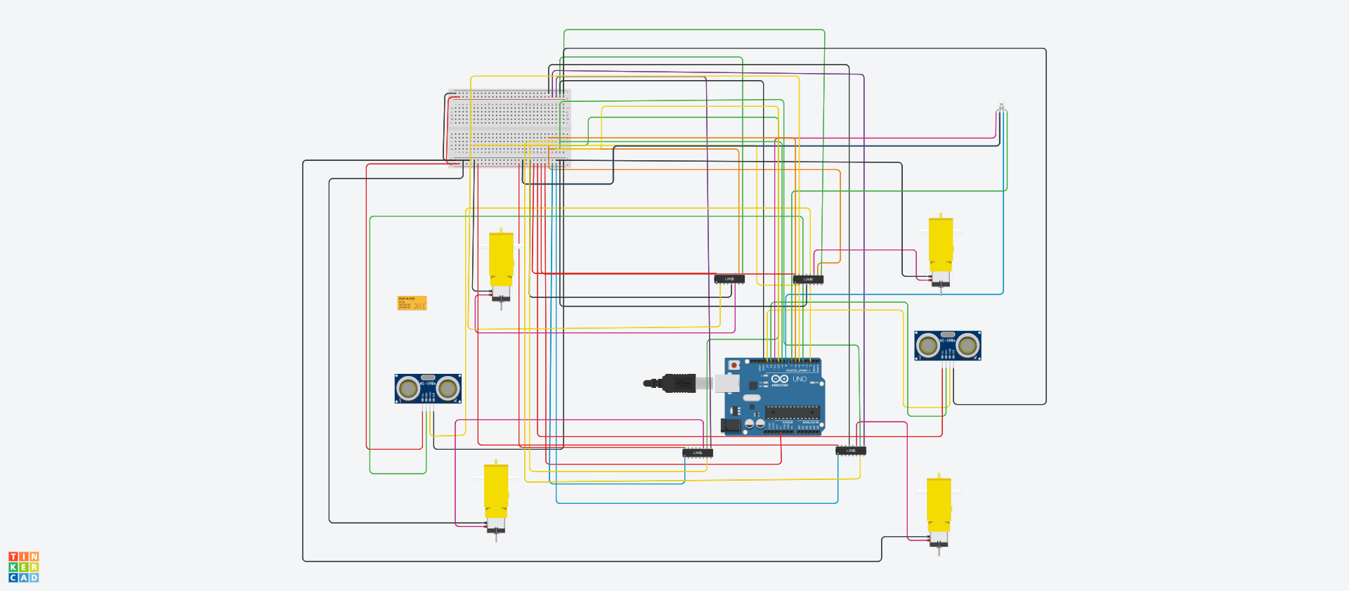
Image 01: Initial Schematic of the Farmaid Bot
BackgroundOur Teamato team came together as a result of the fact that we are all members of the Detroit Autonomous Vehicle Group and the Ann Arbor Autonomous Vehicle Group. These are both Meetup groups. Our team member Sohaib entered the challenge with the above concept and created a post asking if anyone was interested in participating. Alex, Juanito, and David joined with Sohaib and so began a common quest among individuals that had never worked together before.
Beyond finding common ground on approach, tech, timing, etc. we had to lay down a framework of meeting schedules, repositories, conferencing tech, and so on. Essentially, all of the components that go into a professional project had to be put in place, except no one was getting paid, we had no budget, and all had work, school, family, etc. commitments. Not a problem as we shared a mutual vision and the will to execute.
Interestingly our group of four individuals represented an international community. Each member of our team was multi-lingual and had direct family ties to one or more of the following: China, Germany, Pakistan, Philippines, Russia.
We all had a great time and it was an amazing learning experience.
Building the RobotWorking on the chassis, autonomous navigation, and image classifiction began imeediately and progressed at a good pace. Where we ran into major unexpected challenges and delays related to our chassis and drive system. Simply put we did not anticipate such varying terrains among the test greenhouses, and motors, wheels, wiring, controls, etc. that were fine in scenario A were overwhelmed in scenario B.
We went through a large number of mods to dial-in a workable chassis for all of our environments. We had to make a lot of time and budget constraints but the end product exceeded our initial goal of a minimum viable configuration. The final design at the time of submission is described below.
Camera Pole
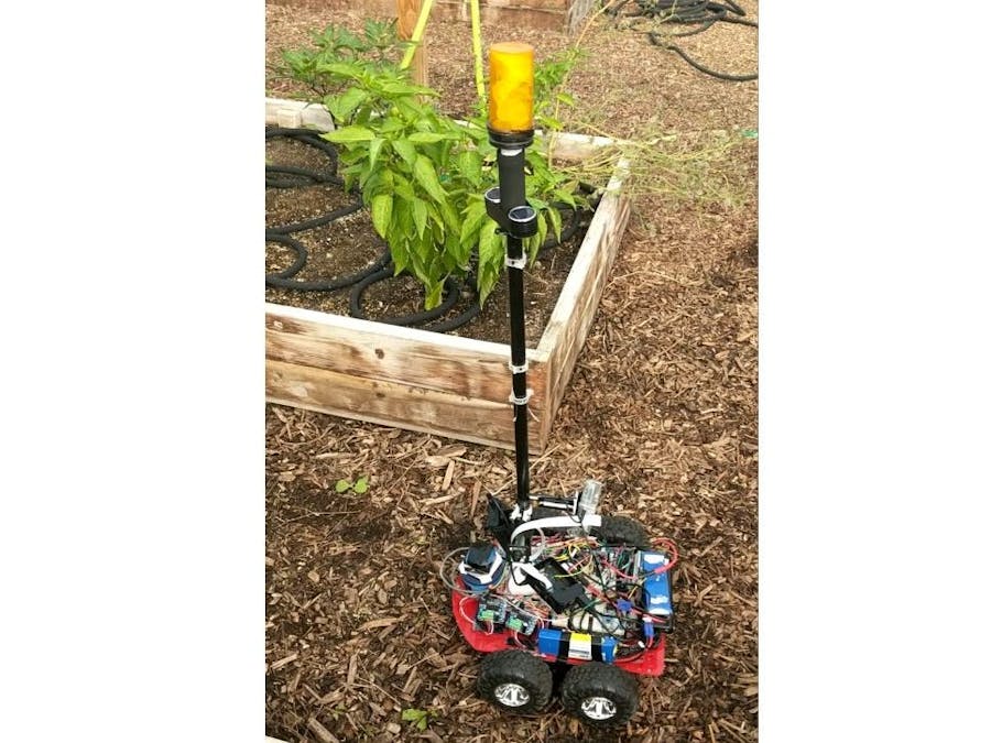
To be able to look at raised beds of plants and potentially upgrade to a moving camera that could look at the top and bottom of tomato plants, we built a camera pole using a carbon fiber rod bought from a garage sale.
The rod was fitted with 2 3D printed clamps for the navigation and classification cameras. We also added 1.2v solar lighting to the pole, as well as, 12v multicolor status lights on top of the pool. Yes, that is a repurposed pill container painted black on top of the pole. One of our many zero-based budget accomodations that worked just great!
The cameras were Raspberry Pi Cameras attached to two different pi's powered by USB chargers. The reason for using 2 Pi's is that both classification and navigation use a neural network which takes a lot of processing power. Additionally, the classification camera had to point towards the plants while the navigation camera had to point in front.
The top of the pole also had to have lights to serve as indicators. Upon searching for RGB lights that would be bright enough, we found they would cost upwards of $100 so we made our own using lights from a speaker, a small plastic bag for reflection and encased in an empty pill bottle.
Since the lights required 12 Volts and our Arduino output was 5 volts, we connected it to a relay
The connection required a common ground with the Arduino and 3 wires for the red, green and blue lights which we placed at pins 7, 8 and 11 on the Arduino. We could simulate the RGB spectrum on these lights by using analogWrite function to give different values to all three wires. Note that for correct coloring, all three need to be written otherwise a previously written color on any one pin could show unexpected results.
Chassis
Our experiments with a plastic chassis with both wheels and tracks using low power motors had proven unsuccessful at location at Stone Coop and Growing Hope farms and both options would trench into sandy ground that is beneficial for plants.
One of our interim chassis versions, we stripped a lot of plastic gears before upgrading to metal and the ability to handle higher current:
We eventually settled on the Mountain Ark SR13 chassis due to its powerful motors and large wheels and assembled it using the instructions below.
We modified the Mountain Ark, added a platform to divide power from computing tech, and gave Farmaid a touch of style with a custome painted lightweight cover and unique logo.
After assembling the chassis we needed motors and a battery to power it.
While the chassis came with a battery case, we decided on using a 12V LiPo battery as we already had that available and had used it with the older chassis.
The motors were connected to the battery using a terminal block for the higher current draw required.
We initially used a normal L298 motor controller that we had but found out that the current was too low to power the 320 RPM motors we had now. We thus switched to IBT-2 motor controllers, that another member of the makerspace donated. The problem with IBT-2 motor controllers is that they can only control 1 motor so we had to connect 4 of them. Details of the IBT-2 can be seen here:
http://www.hessmer.org/blog/2013/12/28/ibt-2-h-bridge-with-arduino/
To save on wiring space, we spliced the left and right PWM wires, the splice connected the L-PWM and R-PWM of the motors on the left and the motors on the right to each other.
Another space saving technique we used was to directly connect the enable pins of all motors to the 5 volts from the Arduino.
After this, the only part of the motors we needed to connect directly to the Arduino were the PWM pins. On the left side, we connected the R_PWM of the left motor to the 6 pin on the Arduino and the L_PWM to the 5 pin. Note that the R_PWM pins of both controllers on the left and the L_PWM on both controllers on the left were spliced so a forward command to one, would move both forward and a reverse command to one would reverse both wheels on the left. The same splicing was done on the right. The R_PWM on the right was connected to the 9 pin on the Arduino and the L_PWM was connected to pin 10 on the Arduino.
For collision detection we first tried a Garmin Lidar one of our group members already had but we had difficulty making it work so we settled on using an SR04 ultrasonic sensor instead. Its echo pin was connected to the pin 12 and the trigger pin was connected to pin 13 on the Arduino.
We also added another sensor at the back but due to the way timer interrupts are used, we could not use it while also doing manual control of the robot. Note that we made another Arduino routine to move the robot between obstacles using only the sensors but it was not in line with the behavior cloning approach.
Since we could not use a chassis similar to the Donkey Car due to the fact that it could not drive in our given environment, we had to write our own driving code.
For this we used two inspirations, the Donkey Car's own method as well as a series of videos by YouTuber Sentdex
The driving model was based on the Donkey Car except instead of regression and mean squared error, we used classification to classify between 7 buttons using an image. We also converted it into a fully convolutional neural network to make it faster and inline with newer research.
Upon testing, we found that since it constantly output a button unlike in training where we pressed a key after a few intervals. To remedy this, we later added some code in the Arduino script to output the time elapsed between button presses. This was used to add another branch to the network that would do regression and output the resulting key after the given amount of time.
Classification of Diseased Plants:For classification we used the MobileNet SSD model due to its relatively small size and the fact that it already had a method to upload to an android app.
We got the data by using 5-10 second videos and created a script to extract images from these videos. The videos themselves had been places in folders named after the disease and the plant. We made sure to take these videos under different conditions and at different locations. The total training dataset consisted of about 2000 images.
We also made a website to show the output of the classification and the the overall map of the greenhouse and its plant health. The website uses XML data to create this grid. We did not have time to add real time updates to the website from the classifier but it is one of our future goals.
We also tested SMS system by Twillo to send a message to a phone when the plant disease is above a given threshold. Again due to time constraints, we have not connected it to the classifier yet.
Interesting side notes:Greenhouse work can get rather warm, actual picture from one of our testing days.
We also made it a point during the project to take Farm Aid out to public events whenever asked to do so.
At one event our Farmaid bot even met some bot friends including Mowbot and some high power bots. Synergy for future builds and collaboration!


Comments
Please log in or sign up to comment.