

Hardware components | ||||||
| × | 1 | ||||
| × | 1 | ||||
Software apps and online services | ||||||
 |
| |||||
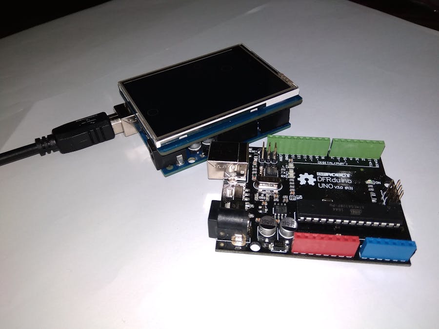
The shield is fully assembled, tested and ready to go. No wiring, no soldering! Simply plug it in and load up our library - you'll have it running in under 10 minutes! This Fantastic TFT display is big (2.8" diagonal) bright (4 white-LED backlight) and colorful (18-bit 262,000 different shades)! 240x320 pixels with individual pixel control. It has way more resolution than a black and white 128x64 display. As a bonus, this display comes with a resistive or capacitive touchscreen attached to it already, so you can detect finger presses anywhere on the screen.
- 2.8"
- 240x320
- CPU Interface: SPI
- Free 11 pins on the Arduino header
- 4 MB flash and micro-SD card
- 3.3V and 5.0V Input voltage compatible
- Support Universal TFT library: UTFT
There's two versions of the shield. One has a resistive touch screen, one has a capacitive one. The TFT display and pinouts is the same for both. The microSD card is the same too. The differences come in on the touch screen controller.
- Digital #13 or ICSP SCLK - This is the hardware SPI clock pin. By default its digital #13. By cutting a jumper and soldering another on the back, you can move this line from #13 to the ICSP clock pin. This pin is used for the TFT, microSD and resistive touch screen data clock
- Digital #12 or ICSP MISO - This is the hardware SPI master-in-slave-out pin. By default its digital #12. By cutting a jumper and soldering another on the back, you can move this line from #12 to the ICSP MISO pin. This pin is used for the TFT, microSD and resistive touch screen data
- Digital #11 or ICSP MOSI - This is the hardware SPI master-out-slave-in pin. By default its digital #11. By cutting a jumper and soldering another on the back, you can move this line from #11 to the ICSP MOSI pin. This pin is used for the TFT, microSD and resistive touch screen data
- Digital #10 - This is the TFT CS (chip select pin). It's used by the Arduino to tell the TFT that it wants to send/receive data from the TFT only
- Digital #9 - This is the TFT DC (data/command select) pin. It's used by the Arduino to tell the TFT whether it wants to send data or commands
- Digital #13 or ICSP SCLK - This is the hardware SPI clock pin. By default its digital #13. By cutting a jumper and soldering another on the back, you can move this line from #13 to the ICSP clock pin. This pin is used for the TFT, microSD and resistive touch screen data clock
- Digital #12 or ICSP MISO - This is the hardware SPI master-in-slave-out pin. By default its digital #12. By cutting a jumper and soldering another on the back, you can move this line from #12 to the ICSP MISO pin. This pin is used for the TFT, microSD and resistive touch screen data
- Digital #11 or ICSP MOSI - This is the hardware SPI master-out-slave-in pin. By default its digital #11. By cutting a jumper and soldering another on the back, you can move this line from #11 to the ICSP MOSI pin. This pin is used for the TFT, microSD and resistive touch screen data
- Digital #8 - This is the STMPE610 Resistive Touch CS (chip select pin). It's used by the Arduino to tell the Resistive controller that it wants to send/receive data from the STMPE610 only
- SDA - This is the I2C data pin used by the FT6206 capacitive touch controller chip. It can be shared with other I2C devices. On UNO's this pin is also known as Analog 4.
- SCL - This is the I2C clock pin used by the FT6206 capacitive touch controller chip. It can be shared with other I2C devices. On UNO's this pin is also known as Analog 5.
- Digital #13 or ICSP SCLK - This is the hardware SPI clock pin. By default its digital #13. By cutting a jumper and soldering another on the back, you can move this line from #13 to the ICSP clock pin. This pin is used for the TFT, microSD and resistive touch screen data clock
- Digital #12 or ICSP MISO - This is the hardware SPI master-in-slave-out pin. By default its digital #12. By cutting a jumper and soldering another on the back, you can move this line from #12 to the ICSP MISO pin. This pin is used for the TFT, microSD and resistive touch screen data
- Digital #11 or ICSP MOSI - This is the hardware SPI master-out-slave-in pin. By default its digital #11. By cutting a jumper and soldering another on the back, you can move this line from #11 to the ICSP MOSI pin. This pin is used for the TFT, microSD and resistive touch screen data
- Digital #4 - This is the uSD CS (chip select pin). It's used by the Arduino to tell the uSD that it wants to send/receive data from the uSD only
No wiring, no soldering! Bam!
This TFT is about the same size as an Arduino, we pre-assemble the shield in the factory. To use, simply place it onto your Arduino Uno.
The TFT LCD library is based off of the Adafruit GFX graphics core library. GFX has many ready to go functions that should help you start out with your project. Its not exhaustive and we'll try to update it if we find a really useful function. Right now it supports pixels, lines, rectangles, circles, round-rects, triangles and printing text as well as rotation.
We have example code ready to go for use with these TFTs. Libraries need to be downloaded and installed. Such as: dmtftlibrary, Adafruit ILI9341 library, and Adafruit GFX Library!
Especially for first-time library installers, check on YouTube about how to install a library.


Comments
Please log in or sign up to comment.