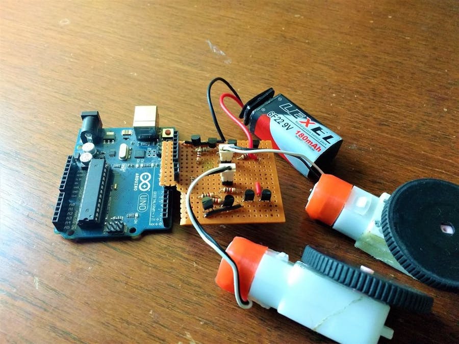
Motors are used from a robot to an autonomous car. You must have to think about adding motors to your projects to make them maneuverable. Driving motors may seem pretty easy at the outset. Just add a motor, connect it to the voltage rail appropriately. But when you are working with several components at the same time, it is not the perfect way to use motors. Thus, we use motor drivers. You can buy them markets but here we will learn how they work and how can we make one at our home.
Motor DriversThe most common type of motors you might have come across is the 3V DC motors which are optimized to work with low voltages. These motors are hobbyists friendly and low cost.
Running them is quite simple. Just connect them with two 1.5 V AA batteries and they will fire up. This setup is good for simple works like making a fan or a miniature windmill. But when it comes to the dynamic applications of them such as robots, more precision is required - in the form of variable speed and torque.
We can decrease the voltage of the input source to decrease the speed of the motor. That's intuitive! But if the motors are connected to the common voltage source, we need a circuit to change the voltage using a proper driving circuit.
Variable linear voltage regulators like LM317 can be used to increase or decrease the voltage and a few bipolar transistors can be added to increase the current supply if required. But the biggest drawback of this is that thetransistordissipatespowerandtheefficiencyofthedriverdecreases.
The solution to this problem is the method of PWM or pulsewithmodulation. Here, the motor is driven by a square wave with an adjustable duty cycle (ratio of the on-time to the period of the signal). The total power delivered is proportional to the duty cycle. In other cycles, the motor is powered for a small fraction of the time period – so over time, the average power to the motor is low. With a 0% duty cycle, the motor is off (no current flowing); with a duty cycle of 50% the motor runs at half power (half the current draw) and 100% represents full power at the maximum current draw.
This is implemented by connecting the motor high side and driving it with an N-channel MOSFET, which is driven again by a PWM signal.
This has some interesting implications – a 3V motor can be driven using a 12V supply using a low duty cycle since the motor sees only the average voltage. With careful design, this eliminates the need for a separate motor power supply.
What if we need to reverse the direction of the motor? This is usually done by switching the motor terminals, but this can be done electrically.
One option could be to use another FET and a negative supply to switch directions. This requires one terminal of the motor to be permanently grounded and the other connected to either the positive or negative supply. Here, the MOSFETs act like an SPDT switch.
However, a more elegant solution exists.
The H-Bridge Motor Driver CircuitThis circuit is called H-bridge because the MOSFETs form the two vertical strokes and the motor forms the horizontal stroke of the alphabet ‘H’. It is a simple and elegant solution to all motor driving problems. The direction can be changed easily and the speed can be controlled.
In an H-bridge configuration, only the diagonally opposite pairs of MOSFETs are activated to control the direction, as shown in the below figure:
When activating one pair of (diagonally opposite) MOSFETs, the motor sees current flow in one direction and when the other pair is activated, the current through the motor reverses direction.
The MOSFETs can be left on for full power or PWM-ed for power regulation or turned off to let the motor stop. Activating both the bottom and top MOSFETs (but never together) brakes the motor.
Components RequiredFor the H-Bridge
- DC motor
- 2x IRF3205 N-channel MOSFETs or equivalent
- 2x IRF5210 P-channel MOSFETs or equivalent
- 2x 10K resistors (pulldown)
- 2x 100uF electrolytic capacitors (decoupling)
- 2x 100nF ceramic capacitors (decoupling)
For the Control Circuit
- 1x 555 timer (any variant, preferably CMOS)
- 1x TC4427 or any appropriate gate driver
- 2x 1N4148 or any other signal/ultrafast diode
- 1x 10K potentiometer (timing)
- 1x 1K resistor (timing)
- 4.7nF capacitor (timing)
- 4.7uF capacitor (decoupling)
- 100nF ceramic capacitor (decoupling)
- 10uF electrolytic capacitor (decoupling)
- SPDT switch
Now that we’ve got the theory out of the way, it’s time to get our hands dirty and build an H-bridge motor driver. This circuit has enough power to drive medium-sized motors up to 20A and 40V with proper construction and heatsinking. Some features have been simplified, like the usage of an SPDT switch to control the direction.
Also, the high side MOSFETs are P-channel for simplicity. With the appropriate driving circuit (with bootstrapping), N-channel MOSFETs could also be used.
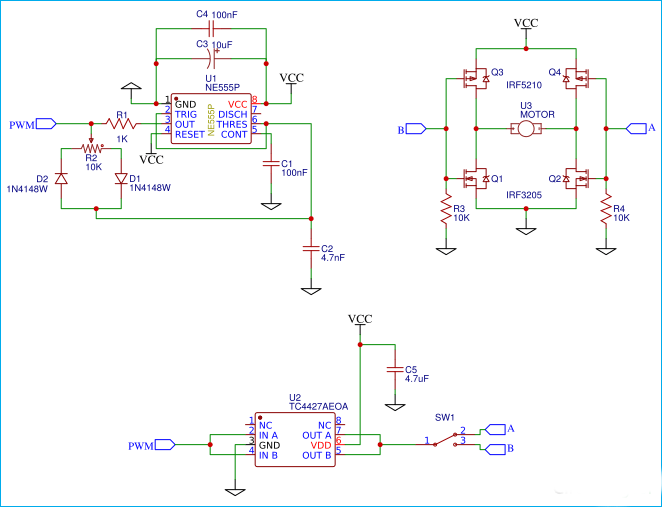
The complete circuit diagram for this H-Bridge using MOSFETs is given below:
1. The 555 Timer
The timer is a simple 555 circuit that generates a duty cycle from around 10% to 90%. The frequency is set by R1, R2, and C2. High frequencies are preferred to reduce audible whining, but this also means that a more powerful gate driver is needed. The duty cycle is controlled by potentiometer R2.
This circuit can be replaced by any other PWM source like an Arduino.
2. Gate Driver
The gate driver is a standard two-channel TC4427, with 1.5A sink/source per channel. Here, both the channels have been paralleled for more driving current. Again, if the frequency is higher the gate driver needs to be more powerful.
The SPDT switch is used to select the leg of the H-bridge which controls the direction.
3. H-Bridge
This is the working part of the circuit that controls the motor. The MOSFET gates are normally pulled low by the pulldown resistor. This results in both the P- channel MOSFETs turning on, but this is not a problem since no current can flow. When the PWM signal is applied to the gates of one leg, the N and P-channel MOSFETs are turned on and off alternately, controlling the power.
H-Bridge Circuit Construction TipsThe biggest advantage of this circuit is that it can be scaled to drive motors of all sizes, and not only motors – anything else that needs a bidirectional current signal, like sine wave inverters.
When using this circuit even at low powers, properly localized decoupling is a must unless you want your circuit to be glitchy.
Also, if constructing this circuit on a more permanent platform like a PCB, a large ground plane is recommended, keeping the low current parts away from the high current paths.
So this simple H-Bridge circuit is the solution for many motor driving problems like bidirectionally, power management and efficiency.


Comments