We have seen many DIY water level indicators which are made using Arduino UNO or any other microcontrollers. This adds up to the list of components and the budget too. If you want a cheap device for indicating the water levels of any water storage tank, we would need a good cheaper alternative.
This project is all about making such water level indicator that can give you very accurate and reliable output. Even though the fact is that the device itself doesn't utilise any of the microcontroller or programming firmware. Therefore, if you don't like setting up things for software and programming microcontrollers, you can just solder a few components in an hour and your water level indicator is ready.
Concept & WorkingNPNTransistorasaSwitch
A transistor can be used for switching operation for the opening or closing of a circuit. This type of solid-state switching offers significant reliability and lower cost when compared to conventional relays.
Both NPN and PNP transistors can be used as switches but here in this project, we are using NPN transistor.
An ideal transistor switch would have infinite circuit resistance between the Collector and Emitter when turned “fully-OFF” resulting in zero current flowing through it and zero resistance between the Collector and Emitter when turned “fully-ON”, resulting in maximum current flow.
In practice when the transistor is turned “OFF”, small leakage currents flow through the transistor and when fully “ON” the device has a low resistance value causing a small saturation voltage (VCE) across it. Even though the transistor is not a perfect switch, in both the cut-off and saturation regions the power dissipated by the transistor is at its minimum.
In order for the Base current to flow, the Base input terminal must be made more positive than the Emitter by increasing it above the 0.7 volts needed for a silicon device. By varying this Base-Emitter voltage VBE, the Base current is also altered and which in turn controls the amount of Collector current flowing through the transistor as previously discussed.
When maximum Collector current flows the transistor is said to be Saturated. The value of the Base resistor determines how much input voltage is required and the corresponding Base current to switch the transistor fully “ON”.
Application of Transistor as a Switch in Project
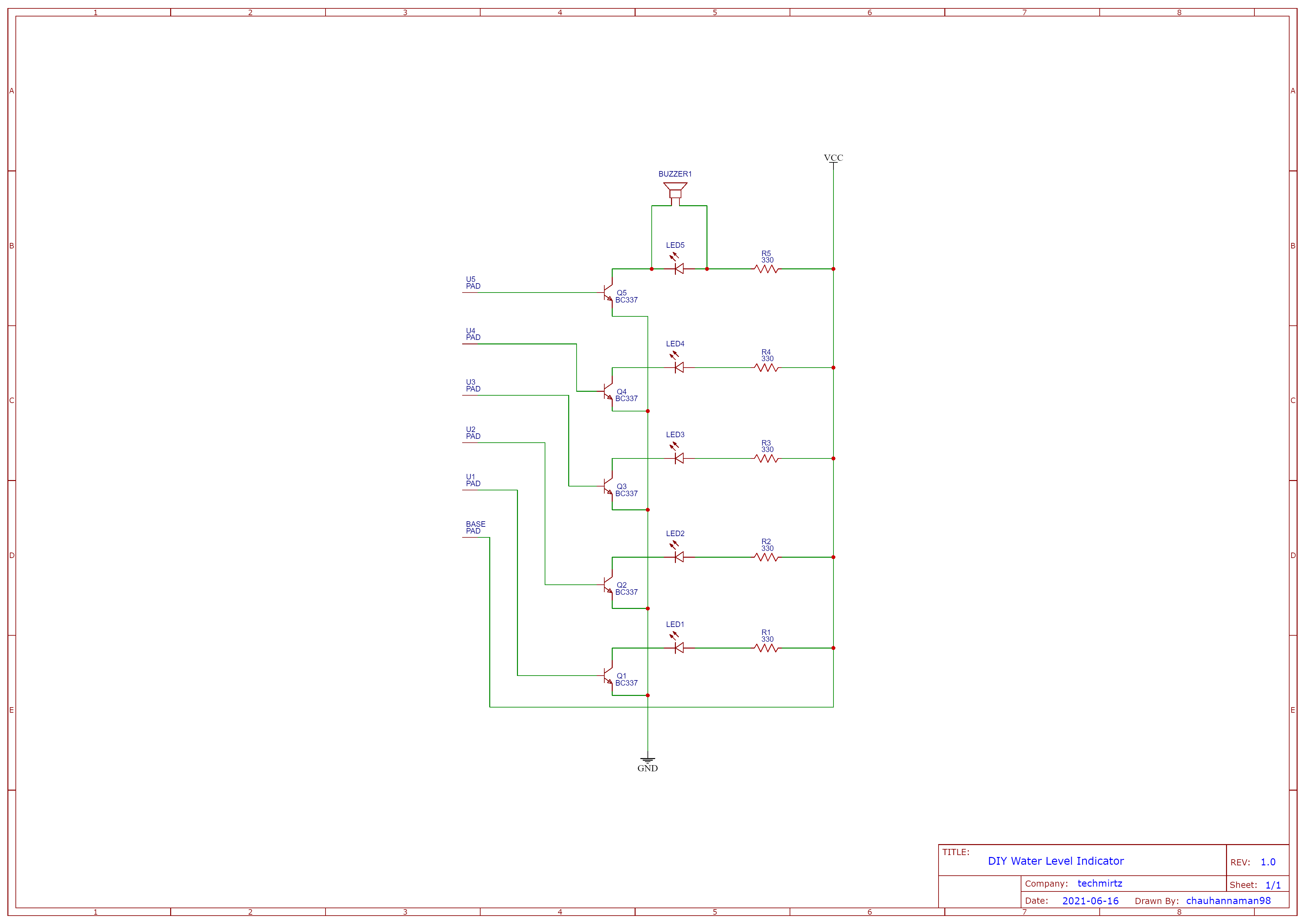
This project uses water as a conducting media for passing minute electric current. There are probes at different depth levels of the tank. There are five different levels for this indicator. The fifth level is the highest one.
- The
BASEconnection of the board is connected to a wire/probe kept in the bottom of the tank. It is connected to the positive(+) terminal. - When water is filled in the tank, the water level rises and when it touches the probe at the lowest level, the current starts conducting from
BASEtoProbe1(20% here). - The probe is connected to the base of the transistor. Here, the transistor works as a switch. When there is no current supply on the base, transistor current won't flow from collector to emitter. But, as the probe supplies current to the base, the transistor comes to the on state and starts conducting current for the collector to emitter.
- Now, as the circuit is complete, the LED starts to glow which shows that the water level has reached
Probe1(25%). - This process continues to all the probe levels-
Probe2(50%),Probe3(75%),Probe4(100%) andProbe5(Overflow-Alarm). - When the level reaches overflow level, apart from LED, a buzzer is connected parallel to it. As the LED glows, the buzzer starts making an alarming sound.
- When the level goes down, the base current stops. Thus, the LED stops glowing and the buzzer stops making the sound.
Follow the below steps to assemble the device at home easily:
- Download the Gerber files for the PCB from here or down below.
- Go to PCBWay.com and upload the files get your PCBs at home at a very low price. Also, you can get a $5 Welcome Bonus. They are the most cost-effective and quality-oriented PCB manufacturers. You can order your prototype PCBs in a small quantity, as small as 5 pcs of PCB. In addition to the standard PCBs, we could also support advanced PCBs, FPC/rigid-flex PCBs and other related services.
- Solder the components on the PCB as per the schematic and design shown below.
- Now, you can connect the probes as per the labels on the PCB to different depths. Probes are nothing but wires connected to the board.
- Put the
BASEprobe at the bottom of the tank.
Note: If the tank is made up of metal, make sure that probes(bare wire) aren't touching the tank. Else, it can give you a false reading.


Comments
Please log in or sign up to comment.