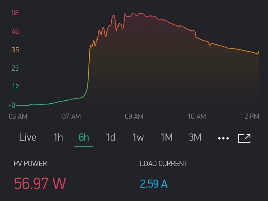
This is an Arduino project to connect a cheap EPSolar / EPEver Tracer A/B or Xtra or Triton Series MPPT Solar Controllers (RS-485 Modbus) to an ESP8266 and monitor it using the Blynk mobile app!
This is complete rewrite of the original project, with ton of improvements, refactored code, brand new Blynk template and graphics, and wider compatibility of RS485 converters.
Turn your cheap $50 MPPT into a web-enabled real-time IoT statistics machine!
You only need any generic ESP8266 board, (I've used NodeMCU), Ethernet cable, cheapo MAX485 module and maybe a USB wall adapter to power the ESP.
Hardwareor
These are the cheap $50 MPPT solar controllers available from usual sources.
So, you will need:
- EPSolar/EPEver Tracer A/B-Series (many, many others will work too)
- RS485 UART Module - I'm using MAX485 cheapo module and it works fine
- ESP8266 Dev Board
- An old Ethernet cable with RJ45 connector you are happy to cut open
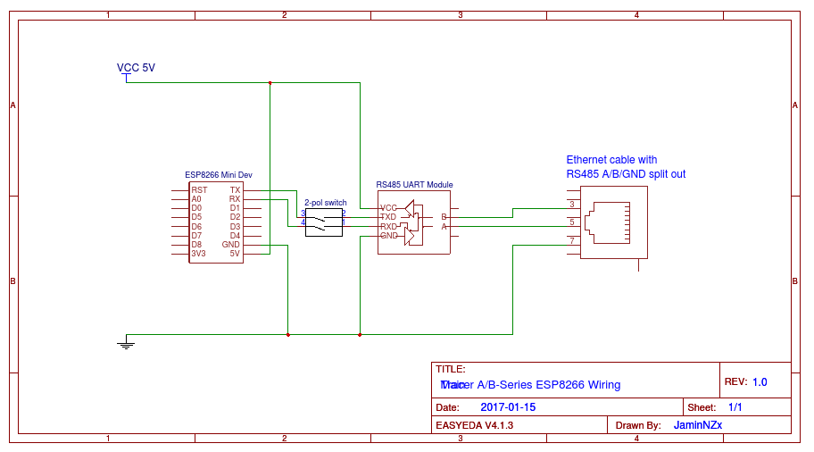
Cut open your Ethernet cable and split out pin 3, 5, 7 (B, A, GND). Refer to Tracer Modbus PDF for additional info.
Follow the wiring guide below: The switch is optional and not needed.
Follow links to get them. (You don't have to download ArduinoOTA, it's part of the ESP8266 Arduino codebase).
TutorialEdit esp_credentials.h libraryFirstly, enter WiFi credentials in esp_credentials.h.
You will be able to use this file by including it in any sketch by entering #include <esp_credentials.h>. (This include is already present in settings.h, there's no need to add it.)
Example:
/**************  Settings - Wifi Credentials  *******************/
#define WIFI_SSID             "xxxxxxxxxxxxxxxxxxxxxxxxxxxxxxxx"
#define WIFI_PASS             "xxxxxxxxxxxxxxxxxxxxxxxxxxxxxxxx"
- Open the Blynk mobile app and create a new project by scanning the following QR code
- Send yourself the generated auth code
- Paste your auth code into
esp_credentials.h:
#define AUTH "xxxxxxxxxxxxxxxxxxxxxxxxxxxxxxxx"
- Upload the sketch to your ESP8266
- Plug the ethernet cable to the Solar controller
- Load the Blynk project and hit PLAY button to start receiving data
- There will be a lot of useful info for debugging available on the USB Serial port of the ESP
I'm using this cheapo module and it works quite fine. It's powered from +5V from ESP8266, and wired as following:
DI->D10/GPIO1/TXRO->D9/GPIO3/RXDEandREare interconnected with a jumper and then connected do eighter pinD1orD2VCCto+5V/VINon ESP8266
- Ethernet green, pin
5->A - Ethernet blue, pin
3->B - Ethernet brown, pin
7->GNDon module and ESP8266GNDpin - -> to prevent ground loops - important!
That's it!
You should be now able to see nice stats for different periods and also real-time live data of your panels.
Developing FurtherYou are welcome for suggestions, bugreports, and of course any further improvements of this code.
Credits- Thanks to @jaminNZx for the original idea. Big up!


Comments
Please log in or sign up to comment.