tiktok.com/@embeddedthings
You can access the source code files via this link.
In this project, we will connect multiple displays to the STM32 microcontroller using the 4-bit mode, which requires six GPIO pins. The STM32 operates at 3.3V logic levels, while the displays operate at 5V. However, this is not a problem because the displays can still recognize the 3.3V output from the STM32. The only 5V line that is required is the VDD line for the displays, which can be powered using the 5V pin on the STM32 board. We will simulate this setup using Proteus software. Following this article, we will take the 16x2 LCD as an example to explain how displays work.
Liquid crystal displays (LCDs) are a commonly used to display data in devices such as calculators, microwave ovens, and many other electronic devices, the 16×2 LCD with a 16-pin header interface. Assuming it has the standard Hitachi LCD driver HD44780 controller. We’ll see how it works internally and how to interface it with STM32
LCD Module Pinout:
This is the pinout for a typical LCD 16×2 display unit.
Pins’ Functions Description:
LCD Controller IC:
The LCD module consists of 16×2 character cells, and each one of them is 5×8 dots. Controlling all of this is a tedious task for our main STM32 microcontroller to do. However, it doesn’t have to do. As there is a specific function controller on the LCD itself controlling the display while reading in the user’s commands & data. Here, I’ll be considering the Hitachi HD44780 controller.
Step One:- Open CubeMX & Create New Project Choose The Target MCU STM32F103C6 & Double-Click Its Name
- Go To The Clock Configuration & Set The System Clock To 8MHz
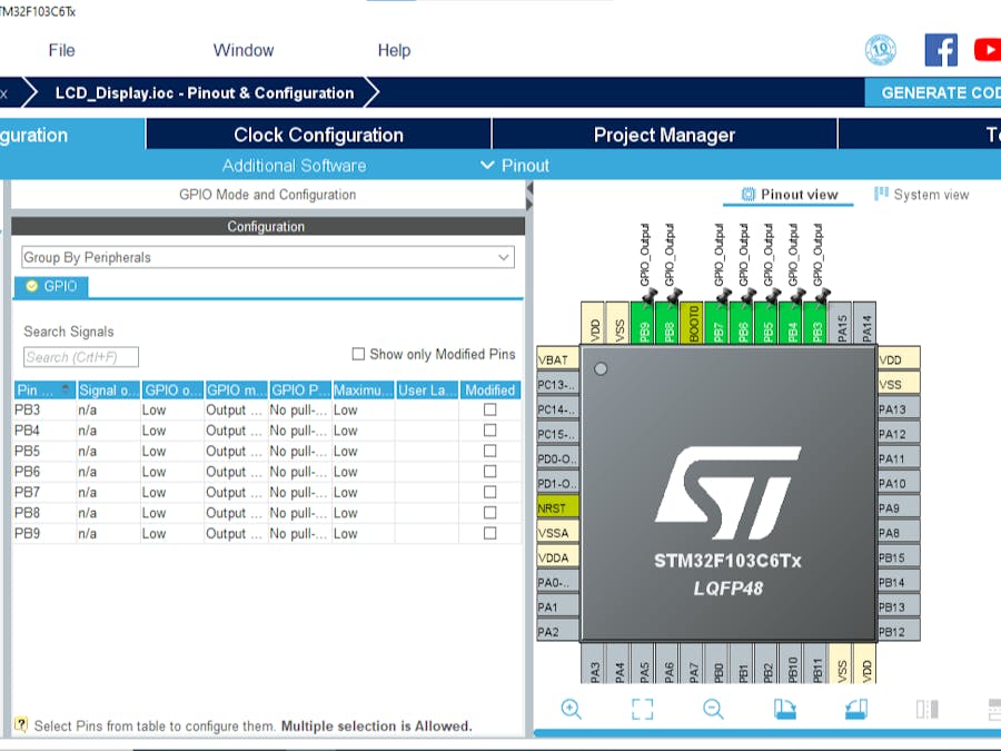
- Configure The GPIO Pins [PB3..PB9] as Output Pins
- Generate The Initialization Code & Open The Project In CubeIDE
- Create header and source file for liquid crystal
- Write The Application Layer Code
In file name : LiquidCrystal.h
In file name : LiquidCrystal.c
In file name :main.c
Step Two:- Open Proteus & Create New Project and click next
- Click on Pick Device
- Search for STM32F103C6 & [LCD 16*2... LCD 20*4]
- Click on Terminal Mode then choose (DEFAULT & POWER &GROUND)
- finally make the circuit below and start the simulation
If you have any questions or suggestions don't hesitate to leave a comment below


Comments
Please log in or sign up to comment.