


Hardware components | ||||||
 |
| × | 1 | |||
| × | 1 | ||||
| × | 1 | ||||
Software apps and online services | ||||||
 |
| |||||
| ||||||
This is my second project with Google Summer of Code (GSoC) under TensorFlow. There was no proper documentation on the internet to build a custom image recognition TinyML model, so my GSoC mentor, Paul Ruiz, suggested that I should try and solve it. Here's how you could also build an image recognition TinyML application. Happy Tinkering!
Click here to view my first GSoC project!The idea behind the project:
I wanted to work on a problem with fewer variables as the documentation for how to work with the camera module and process its data wasn't great. I choose to build an MNIST TinyML model as, in this case, I wouldn't need to worry about the training data set, and it would allow me to focus on the essential parts of the project to get things up and running. But, now that I have figured out all the parts to build a custom image recognition project, I have documented how to collect training data sets using the camera module.
The theme/tone for the blog?I want to warn you that this blog might get a bit complex to understand. There's a proper explanation for this: With an accelerometer-based application, it would be easy to do sanity checks by just printing out the accelerometer values of one axis on the serial monitor or plotter. In contrast, doing sanity checks for the image recognition application is at least 10x more tiresome because checking if a piece of code is doing the desired action cannot be visualized in real-time.
Some CommentsThis blog might be a bit hard to understand due to the complexity of unit testing. I want to address any gaps in explanation with feedback from the readers. So, comment below with your doubts and questions regarding anything related to image recognition on embedded systems.
Does TinyML make sense at all?I would recommend you to read through this fantastic article by Pete Warden, The author of the TinyML book, to understand why running machine learning models on microcontrollers makes sense and is the future of machine learning.
Even if TinyML makes sense, does image recognition make sense on TinyML?The full VGA (640×480 resolution) output from the OV7670 camera we'll be using here is too big for current TinyML applications. uTensor runs handwriting detection with MNIST that uses 28×28 images. The person detection example in the TensorFlow Lite for Microcontrollers example uses 96×96 which is more than enough. Even state-of-the-art 'Big ML' applications often only use 320×320 images. In conclusion, running image recognition applications on tiny microcontrollers makes a lot of sense
- Wiring
- Introduction to the OV7670 camera module
- RGB888 vs RGB565
- Conclusion
1.a Arduino Nano 33 BLE Sense pinouts
1.b Schematics
1.c Arduino Nano 33 BLE Sense - OV7670 Camera module
Pins on OV7670 Camera Module - Pins on Arduino Nano 33 BLE Sense
3.3 to 3.3V
GND to GND
SIOC to A5
SIOD to A4
VSYNC to 8
HREF to A1
PCLK to A0
XCLK to 9
D7 to 4
D6 to 6
D5 to 5
D4 to 3
D3 to 2
D2 to 0 / RX
D1 to 1 / TX
D0 to 10
1.d Arduino Nano 33 BLE Sense - TFT LCD module
Pins on 1.44" TFT LCD display - Pins on Arduino Nano 33 BLE Sense
Note: there's only one 3.3V on the Arduino board. Use a breadboard to have multiple connections to it.
LED to 3.3V
SCK to 13
SDA to 11
A0 to A6
RESET to 7
CS to A7
GND to GND
VCC to 5V
Note: The TFT LCD module connected to the Arduino board uses the hardware SPI pins.
SPI stands for Serial Peripheral Interface. It is used by the microcontrollers to communicate with one or more peripheral devices quickly. SPI communication is faster than I2C communication.
There are three common pins to all the peripheral devices:
SCK - It stands for Serial Clock. This pin generates clock pulses, that is used to synchronize the transfer of data.
MISO - It stands for Master Input/ Slave Output. This data line in the MISO pin is used to send the data to the master.
MOSI - It stands for Master Output/ Slave Input. This line is used for sending data to the slaves/peripheral devices.
SPI pins on the board:
- D13 - SCK
- D12 - MISO
- D11 - MOSI
We will only use the SCK and MOSI pins here as we'll be sending data to the TFT and won't need the MISO pin for the same.
2.a General information about the OV7670 module
The OV7670 camera module is a low-cost 0.3-megapixel CMOS color camera module. It can output a 640x480 VGA resolution image at 30fps.
Features:
- High sensitivity for low-light operation
- Low operating voltage for embedded portable apps
- Lens shading correction
- Flicker (50/60 Hz) auto-detection
- De-noise level auto adjust
- Supports image sizes: VGA, CIF, and any size scaling down from CIF to 40x30
- VarioPixel method for sub-sampling
- Automatic image control functions include: automatic exposure control (AEC), automatic gain control (AGC), automatic white balance(AWB), automatic band filter (ABF), and automatic black-level calibration (ABLC)
- ISP includes noise reduction and defect correction
- Supports LED and flash strobe mode
- Supports scaling
- Output support for Raw RGB, RGB (GRB 4:2:2, RGB565/555/444), YUV (4:2:2) and YCbCr (4:2:2) formats
- Image quality controls include color saturation, hue, gamma, sharpness (edge enhancement), and anti-blooming
- Saturation level auto adjust (UV adjust)
- Edge enhancement level auto adjust
Specifications:
- Photosensitive Array: 640 x 480.
- IO Voltage: 2.5V to 3.0V.
- Operating Power: 60mW/15fpsVGAYUV.
- Sleeping Mode: <20μA.
- Operating Temperature: -30 to 70 deg C.
- Output Format: YUV/YCbCr4:2:2 RGB565/555/444 GRB4:2:2 Raw RGB Data (8 digit).
- Lens Size: 1/6″.
- Vision Angle: 25 degrees.
- Max. Frame Rate: 30fps VGA.
- Sensitivity: 1.3V / (Lux-sec).
- Signal to Noise Ratio: 46 dB.
- Dynamic range: 52 dB.
- Browse Mode: By row.
- Electronic Exposure: 1 to 510 rows.
- Pixel Coverage: 3.6μm x 3.6μm.
- Duck Current: 12 mV/s at 60℃.
- PCB Size (L x W): Approx. 1.4 x 1.4 inch / 3.5 x 3.5 cm.
2.b Software Setup: Installing the "Arduino_OV767x" library
First you will need the Arduino IDE installed. Next, under the Tools section, click the Manage Libraries, search for OV7670, select the Arduino_OV767x library and click Install.
Supported image configurations in the OV767X library:
- VGA – 640 x 480
- CIF – 352 x 240
- QVGA – 320 x 240
- QCIF – 176 x 144
2.c Software Setup: Installing Processing
Processing is a simple programming environment that was created by graduate students at MIT Media Lab to make it easier to develop visually oriented applications with an emphasis on animation and providing users with instant feedback through interaction.
Download and install Processing using this link.
Why do I need to download this software? We'll use this application to visualize the camera output sent via the serial port by the OV7670 camera module.
2.d Using Processing: Test pattern
Github Link for this subsection.
Open an Arduino sketch, and copy and paste the below sketch into the sketch, upload it to your board.
Processing_test_pattern.ino:
/*
  Circuit:
    - Arduino Nano 33 BLE board
    - OV7670 camera module:
      - 3.3 connected to 3.3
      - GND connected GND
      - SIOC connected to A5
      - SIOD connected to A4
      - VSYNC connected to 8
      - HREF connected to A1
      - PCLK connected to A0
      - XCLK connected to 9
      - D7 connected to 4
      - D6 connected to 6
      - D5 connected to 5
      - D4 connected to 3
      - D3 connected to 2
      - D2 connected to 0 / RX
      - D1 connected to 1 / TX
      - D0 connected to 10
*/

#include <Arduino_OV767X.h>

int bytesPerFrame;

byte data[320 * 240 * 2]; // QVGA: 320x240 X 2 bytes per pixel (RGB565)

void setup() {
  Serial.begin(115200);
  while (!Serial);

  if (!Camera.begin(QVGA, RGB565, 1)) {
    Serial.println("Failed to initialize camera!");
    while (1);
  }

  bytesPerFrame = Camera.width() * Camera.height() * Camera.bytesPerPixel();

  Camera.testPattern();
}

void loop() {
  Camera.readFrame(data);

  Serial.write(data, bytesPerFrame);
}
Once you are done uploading the above sketch to your Arduino board, open the Processing application and copy-paste the below code into a new file.
processingSketch:
import processing.serial.*;
import java.nio.ByteBuffer;
import java.nio.ByteOrder;

Serial myPort;

// must match resolution used in the sketch
final int cameraWidth = 320;
final int cameraHeight = 240;

final int cameraBytesPerPixel = 2;

final int bytesPerFrame = cameraWidth * cameraHeight * cameraBytesPerPixel;

PImage myImage;

void setup()
{
  size(320, 240);

  // if you have only ONE serial port active
  //myPort = new Serial(this, Serial.list()[0], 9600); // if you have only ONE serial port active

  // if you know the serial port name
  //myPort = new Serial(this, "COM5", 9600);                    // Windows
  //myPort = new Serial(this, "/dev/ttyACM0", 9600);             // Linux
  myPort = new Serial(this, "/dev/cu.usbmodem14101", 9600);  // Mac

  // wait for full frame of bytes
  myPort.buffer(bytesPerFrame);

  myImage = createImage(cameraWidth, cameraHeight, RGB);
}

void draw()
{
  image(myImage, 0, 0);
}

void serialEvent(Serial myPort) {
  byte[] frameBuffer = new byte[bytesPerFrame];

  // read the saw bytes in
  myPort.readBytes(frameBuffer);

  // create image to set byte values
  PImage img = createImage(cameraWidth, cameraHeight, RGB);

  // access raw bytes via byte buffer
  ByteBuffer bb = ByteBuffer.wrap(frameBuffer);
  bb.order(ByteOrder.BIG_ENDIAN);

  int i = 0;

  img.loadPixels();
  while (bb.hasRemaining()) {
    // read 16-bit pixel
    short p = bb.getShort();

    // convert RGB565 to RGB 24-bit
    int r = ((p >> 11) & 0x1f) << 3;
    int g = ((p >> 5) & 0x3f) << 2;
    int b = ((p >> 0) & 0x1f) << 3;

    // set pixel color
    img.pixels[i++] = color(r, g, b);
  }
  img.updatePixels();

  // assign image for next draw
  myImage = img;
}
Now, uncomment the line, specific to your operating system, in the above. and Click on the Run button.
// if you know the serial port name
  //myPort = new Serial(this, "COM5", 9600);                    // Windows
  //myPort = new Serial(this, "/dev/ttyACM0", 9600);             // Linux
  //myPort = new Serial(this, "/dev/cu.usbmodem14101", 9600);  // Mac
You should get an output like the one below:
2.e Explanation: Test Pattern
Processing_test_pattern.ino:
byte data[320 * 240 * 2]; // QVGA: 320x240 X 2 bytes per pixel (RGB565)This line of code sets up an array of type byte. We'll be using the RGB565 color formal, so we'll need 2 bytes for every pixel, and the image format we'll be using here is QVGA, which is 320x240 pixels in size. Therefore, the size of the array will be the height * width * bytes required for each pixel's color. In practice, it translates to 320 * 240 * 2.
Serial.begin(115200);
  while (!Serial);
This line of code sets up the serial port to transmit data between the computer and the microcontroller.
if (!Camera.begin(QVGA, RGB565, 1)) {
    Serial.println("Failed to initialize camera!");
    while (1);
  }
The above line of code sets up the OV7670 camera module. In this example, we have initialized it to use the QVGA image format and the RGB565 color format.
Camera.testPattern();This line of code sets the camera to send a test image via the serial port.
Camera.readFrame(data);This line of code reads one frame from the camera and stores it in the array we declared before.
Serial.write(data, bytesPerFrame);Finally, this line of code writes the array's values onto the serial monitor.
processingSketch:
// must match resolution used in the sketch
final int cameraWidth = 320;
final int cameraHeight = 240;
These lines of code set up the cameraWidth and cameraHeight to match the size in the Arduino sketch.
// if you know the serial port name
  //myPort = new Serial(this, "COM5", 9600);                    // Windows
  //myPort = new Serial(this, "/dev/ttyACM0", 9600);             // Linux
  //myPort = new Serial(this, "/dev/cu.usbmodem14101", 9600);  // Mac
These lines of code specify the serial port through which data is transmitted between the microcontroller and the computer.
// convert RGB565 to RGB 24-bit
    int r = ((p >> 11) & 0x1f) << 3;
    int g = ((p >> 5) & 0x3f) << 2;
    int b = ((p >> 0) & 0x1f) << 3;
These lines of code convert the RGB565 color format to RGB888 format to display on your computer screen. This will be explained in detail in further sections.
2.f Using Processing: Live image
Github Link for this subsection.
Open an Arduino sketch, and copy and paste the below sketch into the sketch, upload it to your board.
Processing_ov7670_live_image.ino
/*
  Circuit:
    - Arduino Nano 33 BLE board
    - OV7670 camera module:
      - 3.3 connected to 3.3
      - GND connected GND
      - SIOC connected to A5
      - SIOD connected to A4
      - VSYNC connected to 8
      - HREF connected to A1
      - PCLK connected to A0
      - XCLK connected to 9
      - D7 connected to 4
      - D6 connected to 6
      - D5 connected to 5
      - D4 connected to 3
      - D3 connected to 2
      - D2 connected to 0 / RX
      - D1 connected to 1 / TX
      - D0 connected to 10
*/

#include <Arduino_OV767X.h>

int bytesPerFrame;

byte data[320 * 240 * 2]; // QVGA: 320x240 X 2 bytes per pixel (RGB565)

void setup() {
  Serial.begin(115200);
  while (!Serial);

  if (!Camera.begin(QVGA, RGB565, 1)) {
    Serial.println("Failed to initialize camera!");
    while (1);
  }

  bytesPerFrame = Camera.width() * Camera.height() * Camera.bytesPerPixel();

  Camera.testPattern();
}

void loop() {
  Camera.readFrame(data);

  Serial.write(data, bytesPerFrame);
}
Once you are done uploading the above sketch to your Arduino board, open the Processing application and copy-paste the below code into a new file.
processingSketch:
import processing.serial.*;
import java.nio.ByteBuffer;
import java.nio.ByteOrder;

Serial myPort;

// must match resolution used in the sketch
final int cameraWidth = 320;
final int cameraHeight = 240;

final int cameraBytesPerPixel = 2;

final int bytesPerFrame = cameraWidth * cameraHeight * cameraBytesPerPixel;

PImage myImage;

void setup()
{
  size(320, 240);

  // if you have only ONE serial port active
  //myPort = new Serial(this, Serial.list()[0], 9600); // if you have only ONE serial port active

  // if you know the serial port name
  //myPort = new Serial(this, "COM5", 9600);                    // Windows
  //myPort = new Serial(this, "/dev/ttyACM0", 9600);             // Linux
  myPort = new Serial(this, "/dev/cu.usbmodem14101", 9600);  // Mac

  // wait for full frame of bytes
  myPort.buffer(bytesPerFrame);

  myImage = createImage(cameraWidth, cameraHeight, RGB);
}

void draw()
{
  image(myImage, 0, 0);
}

void serialEvent(Serial myPort) {
  byte[] frameBuffer = new byte[bytesPerFrame];

  // read the saw bytes in
  myPort.readBytes(frameBuffer);

  // create image to set byte values
  PImage img = createImage(cameraWidth, cameraHeight, RGB);

  // access raw bytes via byte buffer
  ByteBuffer bb = ByteBuffer.wrap(frameBuffer);
  bb.order(ByteOrder.BIG_ENDIAN);

  int i = 0;

  img.loadPixels();
  while (bb.hasRemaining()) {
    // read 16-bit pixel
    short p = bb.getShort();

    // convert RGB565 to RGB 24-bit
    int r = ((p >> 11) & 0x1f) << 3;
    int g = ((p >> 5) & 0x3f) << 2;
    int b = ((p >> 0) & 0x1f) << 3;

    // set pixel color
    img.pixels[i++] = color(r, g, b);
  }
  img.updatePixels();

  // assign image for next draw
  myImage = img;
}
Now, uncomment the line, specific to your operating system, in the above. and Click on the Run button.
// if you know the serial port name
  //myPort = new Serial(this, "COM5", 9600);                    // Windows
  //myPort = new Serial(this, "/dev/ttyACM0", 9600);             // Linux
  //myPort = new Serial(this, "/dev/cu.usbmodem14101", 9600);  // Mac
You should get an output like the one below:
2.g Explanation: Live image
Processing_ov7670_live_image.ino:
byte data[320 * 240 * 2]; // QVGA: 320x240 X 2 bytes per pixel (RGB565)This line of code sets up an array of type byte. We'll be using the RGB565 color format so we'll need 2 bytes for every pixel and the image format that we'll be using here is QVGA, which is 320x240 pixels in size. Therefore, the size of the array will be the height * width * bytes required for each pixel's color. In practice, it translates to 320 * 240 * 2.
Serial.begin(115200);
  while (!Serial);
This line of code sets up the serial port to transmit data between the computer and the microcontroller.
if (!Camera.begin(QVGA, RGB565, 1)) {
    Serial.println("Failed to initialize camera!");
    while (1);
  }
The above line of code sets up the OV7670 camera module. In this example, we have initialized it to use the QVGA image format and the RGB565 color format.
Camera.testPattern();This line of code sets the camera to send a test image via the serial port.
Camera.readFrame(data);This line of code reads one frame from the camera and stores it in the array we declared before.
Serial.write(data, bytesPerFrame);Finally, this line of code writes the array on the serial monitor.
processingSketch:
// must match resolution used in the sketch
final int cameraWidth = 320;
final int cameraHeight = 240;
These lines of code set up the cameraWidth and cameraHeight to match the size in the Arduino sketch.
// if you know the serial port name
  //myPort = new Serial(this, "COM5", 9600);                    // Windows
  //myPort = new Serial(this, "/dev/ttyACM0", 9600);             // Linux
  //myPort = new Serial(this, "/dev/cu.usbmodem14101", 9600);  // Mac
These lines of code specify the serial port through which data is transmitted between the microcontroller and the computer.
// convert RGB565 to RGB 24-bit
    int r = ((p >> 11) & 0x1f) << 3;
    int g = ((p >> 5) & 0x3f) << 2;
    int b = ((p >> 0) & 0x1f) << 3;
These lines of code convert the RGB565 color format to RGB888 format to display it on your computer screen. This will be explained in detail in further sections.
2.h Problems with this approach,and possible solutions
The processing application displays a zigzag test pattern instead of the actual test pattern and a broken/washed-out image instead of the correct live image. This has been discussed in Github discussions and Arduino forums. I have attached the links to the same below.
Link to the Github discussion
Link to the Arduino forum
Some of the suggested solutions:
1. Use shorter wires
- My take on it: I changed from 20cm wires to 10cm, but it didn't make a difference.
2. Try Ubuntu Linux
3. Change the FPS
- My take on it: I changed it to be 1/5/30 FPS but there was no improvement.
4. Change the Serial Rate
- My take on it: I changed my Serial Rate to 115200 bps from 9600 bps. but there was still no improvement in the problem
A plausible reason for the problem:
- Most people on the forums agree that it's the windows processing speed that causes the issue and that switching to Ubuntu should solve it.
3.a General information about RGB888
The RGB888 color model uses 8 bits to represent each color. The transparency(alpha) value is assumed to be the maximum(255).
The maximum value possible for red, blue, and green colors is 255.
Some examples:
- White: (R, G, B) = (255, 255, 255)
- Black: (R, G, B) = (0, 0, 0)
3.b General information about RGB565
RGB565 is used to represent colors in 16 bits, rather than the 24bit to specify colors. To make full use of the 16 bits, red and blue are encoded in 5 bits and green in 6 bits. This is due to the fact that human eyes have a better capacity to see more shades of green.
The maximum possible values for red and blue values in the RGB565 color format are 31 while the maximum value for the green color is 63.
Fun fact: RGB565 only has 0.39% (65k vs 16m) of the colors of RGB888
3.c Converting RGB888 values to RGB565
/*
Assumption:
r = 8 bits
g = 8 bits
b = 8 bits
*/
rgb565 = ((r & 0b11111000) << 8) | ((g & 0b11111100) << 3) | (b >> 3);
We shift:
- r left by 11 bits, and throw away the last 3 bits
- g left by 5 bits, and throw away the last 2 bits
- b shifted right by 3 bits to throw away the last 3 bits
We finally bitwise OR these 3 to join them into a single 16-bit representation.
Example:
let's convert the white color from RGB888 to RGB565 color space.
Since we already know the maximum possible values possible for both the color spaces, we should expect
- (255, 255, 255) in the RGB888 color space
- (31, 63, 31) in the RGB565 color space
In this problem,
- r = 255 in decimal or 0000000011111111 in binary
- g = 255 in decimal or 0000000011111111 in binary
- b = 255 in decimal or 0000000011111111 in binary
For red:
- r = 0000000011111111
- (r & 0b11111000) = 0000000011111000
- (r & 0b11111000) << 8) = 1111100000000000
For green:
- g = 0000000011111111
- (g & 0b11111100) = 0000000011111100
- ((g & 0b11111100) << 3) = 0000011111100000
For blue:
- b = 0000000011111111
- (b >> 3) = 0000000000011111
Combining these three equations:
- rgb565 = ((r & 0b11111000) << 8) | ((g & 0b11111100) << 3) | (b >> 3);
- rgb565 = ( 1111100000000000 | 0000011111100000 | 0000000000011111)
- rgb565 = 1111111111111111
In RGB565 color space,
- The first 5 bits correspond to the red value
- The next 6 bits correspond to the green value
- the last 5 bits correspond to the blue value
- This translates to (31, 63, 31), which is the expected output!
3.d Converting RGB565 values to RGB888
int r = ((p >> 11) & 0b00011111) << 3;
int g = ((p >> 5) & 0b00111111) << 2;
int b = ((p >> 0) & 0b00011111) << 3;- For red, we left shift by 11 bits, bitwise AND with 0b00011111, and right shift by 3 bits
- For green, we left shift by 5 bits, bitwise AND with 0b00111111, and right shift by 2 bits
- For blue, we left shift by 0 bits, bitwise AND with 0b00011111, and right shift by 3 bits
Example:
let's convert the white color from RGB565 to RGB888 color space.
Since we already know the maximum possible values possible for both the color spaces, we should expect
- (31, 63, 31) in the RGB565 color space
- (248, 252, 248) in the RGB888 color space
Shouldn't we expect (255, 255, 255) in the RGB888 color space?
RGB565 only has 0.39% (65k vs 16m) of the colors of RGB888. Therefore it's unable to cover the entire spectrum of RGB888.
In this problem,
In RGB format, white = 1111111111111111
For red:
- p(here: white) = 1111111111111111
- (p >> 11) = 00011111
- ((p >> 11) & 0b00011111) = 00011111
- (((p >> 11) & 0b00011111) << 3) = 11111000
For green:
- p(here: white) = 1111111111111111
- (p >> 5) = 0000011111111111
- ((p >> 5) & 0b00111111) = 00111111
- (((p >> 5) & 0b00111111) << 2) = 11111100
For blue:
- p(here: white) = 1111111111111111
- (p >> 0) = 1111111111111111
- ((p >> 0) & 0b00011111) = 00011111
- ((p >> 0) & 0b00011111) << 3 = 11111000
Combining these three outputs:
- Final red value = 0b11111000 = 248
- Final green value = 0b11111100 = 252
- Final blue value = 0b11111000 = 248
- This is the expected output!
Link to a RGB565 color picker
RGB88 to RGB565 converter
I thank my GSoC mentor, Paul Ruiz, for guiding me throughout the project!
Links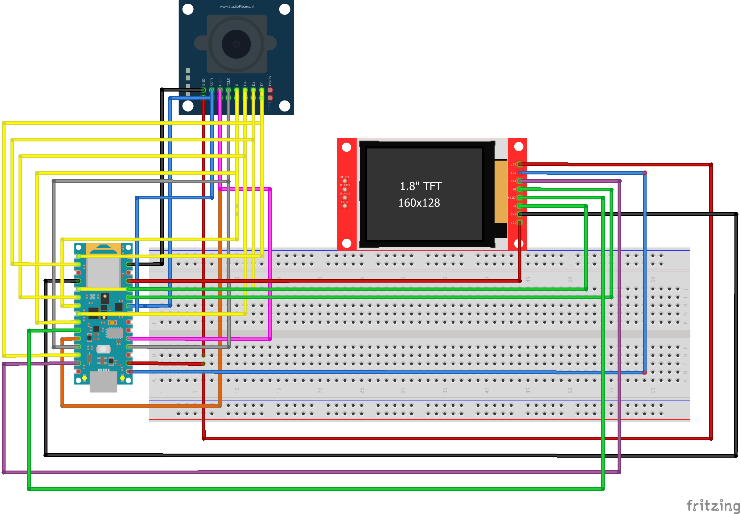


Comments
Please log in or sign up to comment.