

Hardware components | ||||||
 |
| × | 1 | |||
| × | 1 | ||||
| × | 1 | ||||
Software apps and online services | ||||||
 |
| |||||
| ||||||
This is my second project with Google Summer of Code (GSoC) under TensorFlow. There was no proper documentation on the internet to build a custom image recognition TinyML model, so my GSoC mentor, Paul Ruiz, suggested that I should try and solve it. Here's how you could also build an image recognition TinyML application. Happy Tinkering!
Click here to view my first GSoC project!The idea behind the project:
I wanted to work on a problem with fewer variables as the documentation for how to work with the camera module and process its data wasn't great. I choose to build an MNIST TinyML model as, in this case, I wouldn't need to worry about the training data set, and it would allow me to focus on the essential parts of the project to get things up and running. But, now that I have figured out all the parts to build a custom image recognition project, I have documented how to collect training data sets using the camera module.
The theme/tone for the blog?I want to warn you that this blog might get a bit complex to understand. There's a proper explanation for this: With an accelerometer-based application, it would be easy to do sanity checks by just printing out the accelerometer values of one axis on the serial monitor or plotter. In contrast, doing sanity checks for the image recognition application is at least 10x more tiresome because checking if a piece of code is doing the desired action cannot be visualized in real-time.
Some CommentsThis blog might be a bit hard to understand due to the complexity of unit testing. I want to address any gaps in explanation with feedback from the readers. So, comment below with your doubts and questions regarding anything related to image recognition on embedded systems.
Does TinyML make sense at all?I would recommend you to read through this fantastic article by Pete Warden, The author of the TinyML book, to understand why running machine learning models on microcontrollers makes sense and is the future of machine learning.
Even if TinyML makes sense, does image recognition make sense on TinyML?The full VGA (640×480 resolution) output from the OV7670 camera we'll be using here is too big for current TinyML applications. uTensor runs handwriting detection with MNIST that uses 28×28 images. The person detection example in the TensorFlow Lite for Microcontrollers example uses 96×96 which is more than enough. Even state-of-the-art 'Big ML' applications often only use 320×320 images. In conclusion, running image recognition applications on tiny microcontrollers makes a lot of sense
- Reintroductiontothe OV7670 camera module
- Which display to choose?
- Getting started with the OLED module
- Getting started with the TFT LCD module
- Conclusion
4.a Thegame plan /Approach
Now that we have no way of knowing what the camera is looking at or if it's possible to process the camera data to get a meaningful image, how do we move forward?
The approach I used to solve this is to capture a single image, store the pixel values in an array, use code to process(like applying grayscale filters) data from the array, and check if the piece of code is doing the "right" thing by cross verifying it using a visualizer on python.
4.a Gettinghex values via the serial port and visualizing it
Github Link for this subsection.
Copy and paste the below code into a new Arduino sketch, upload it to your board, open the serial monitor, and press c. Copy and paste the hex values into a text file.
Code explanation:
This sketch reads one frame from the camera and prints out the RGB565 values of all the pixels onto the serial monitor.
/*
  OV767X - Camera Test Pattern

  This sketch waits for the letter 'c' on the Serial Monitor,
  it then reads a frame from the OmniVision OV7670 camera and
  prints the data to the Serial Monitor as a hex string.

  The website https://rawpixels.net - can be used the visualize the data:
    width: 176
    height: 144
    RGB565
    Little Endian

  Circuit:
    - Arduino Nano 33 BLE board
    - OV7670 camera module:
      - 3.3 connected to 3.3
      - GND connected GND
      - SIOC connected to A5
      - SIOD connected to A4
      - VSYNC connected to 8
      - HREF connected to A1
      - PCLK connected to A0
      - XCLK connected to 9
      - D7 connected to 4
      - D6 connected to 6
      - D5 connected to 5
      - D4 connected to 3
      - D3 connected to 2
      - D2 connected to 0 / RX
      - D1 connected to 1 / TX
      - D0 connected to 10

  This example code is in the public domain.
*/

#include <Arduino_OV767X.h>

unsigned short pixels[176 * 144]; // QCIF: 176x144 X 2 bytes per pixel (RGB565)

void setup() {
  Serial.begin(9600);
  while (!Serial);

  Serial.println("OV767X Camera Capture");
  Serial.println();

  if (!Camera.begin(QCIF, RGB565, 1)) {
    Serial.println("Failed to initialize camera!");
    while (1);
  }

  Serial.println("Camera settings:");
  Serial.print("\twidth = ");
  Serial.println(Camera.width());
  Serial.print("\theight = ");
  Serial.println(Camera.height());
  Serial.print("\tbits per pixel = ");
  Serial.println(Camera.bitsPerPixel());
  Serial.println();

  Serial.println("Send the 'c' character to read a frame ...");
  Serial.println();
}

void loop() {
  if (Serial.read() == 'c') {
    Serial.println("Reading frame");
    Serial.println();
    Camera.readFrame(pixels);

    int numPixels = Camera.width() * Camera.height();

    for (int i = 0; i < numPixels; i++) {
        unsigned short p = pixels[i];
        if (p < 0x1000) {
          Serial.print('0');
        }
        if (p < 0x0100) {
         Serial.print('0');
        }
        if (p < 0x0010) {
          Serial.print('0');
        }
        Serial.print(p, HEX);
      }
  }
}
Link to the text file with HEX values
4.c ConvertingtheHEXvalues to RGB888 values
Github Link for this subsection.
Copy and paste the below code into a new sketch and upload it to your board.
Code explanation:
This sketch reads one frame from the camera and prints out the RGB888 values of all the pixels onto the serial monitor. The equation used here is extensively described in the earlier sections.
/*
  OV767X - Camera Test Pattern

  This sketch waits for the letter 'c' on the Serial Monitor,
  it then reads a frame from the OmniVision OV7670 camera and
  prints the data to the Serial Monitor as a hex string.

  The website https://rawpixels.net - can be used the visualize the data:
    width: 176
    height: 144
    RGB565
    Little Endian

  Circuit:
    - Arduino Nano 33 BLE board
    - OV7670 camera module:
      - 3.3 connected to 3.3
      - GND connected GND
      - SIOC connected to A5
      - SIOD connected to A4
      - VSYNC connected to 8
      - HREF connected to A1
      - PCLK connected to A0
      - XCLK connected to 9
      - D7 connected to 4
      - D6 connected to 6
      - D5 connected to 5
      - D4 connected to 3
      - D3 connected to 2
      - D2 connected to 0 / RX
      - D1 connected to 1 / TX
      - D0 connected to 10

  This example code is in the public domain.
*/

#include <Arduino_OV767X.h>

uint16_t pixels[176 * 144]; // QCIF: 176x144 X 2 bytes per pixel (RGB565)

void setup() {
  Serial.begin(9600);
  while (!Serial);

  Serial.println("OV767X Camera Capture");
  Serial.println();

  if (!Camera.begin(QCIF, RGB565, 1)) {
    Serial.println("Failed to initialize camera!");
    while (1);
  }

  Serial.println("Camera settings:");
  Serial.print("\twidth = ");
  Serial.println(Camera.width());
  Serial.print("\theight = ");
  Serial.println(Camera.height());
  Serial.print("\tbits per pixel = ");
  Serial.println(Camera.bitsPerPixel());
  Serial.println();

  Serial.println("Send the 'c' character to read a frame ...");
  Serial.println();
}

void loop() {
  if (Serial.read() == 'c') {
    Serial.println("Reading frame");
    Serial.println();
    Camera.readFrame(pixels);

    int numPixels = Camera.width() * Camera.height();

    for (int i = 0; i < 1; i++) {
      for(int j =0; j < 1; j++){
       uint16_t pixel = 512;
       Serial.println(pixel);
       Serial.println(pixel,HEX);
       //RGB888 data
       int red   = ((pixel >> 11) & 0x1f) << 3;
       int green = ((pixel >> 5) & 0x3f) << 2;
       int blue  = ((pixel >> 0) & 0x1f) << 3;
       Serial.println(red);
       Serial.println(green);
       Serial.println(blue);
      }
    }
  }
}
4.d Test:Serial HEX to RGB888
Github Link for this subsection.
One way you can manually check if the equation you've used is working well is to open up the rawpixels.net website and hover your mouse over the image. This would show the RGB values of the pixel of the image. Using the data from this website, you can cross-verify the values that show up on the serial monitor.
4.e Building a custom RG565 visualizer
Github Link for this subsection.
Why did I build a custom RGB565 visualizer?
I was too lazy to save the RGB565 values in a hex file, upload it to the rawpixels website and change the parameters every time to view a single image.
Code explanation:
string = "0D2AED29ED....B6B5B6B5"This line of code stores all the RGB565 values as a string.
(len(string) * 4)

>>405504
Since each hex is equivalent to four binary digits, multiplying the length of the string by 4 gives us the total no of bits to process.
(len(string) * 4) / 16

>> 25344.0
Since each pixel requires 16 bits to represent its color, dividing the total no of bits by 16 gives us the no of pixels to process.
The output here comes out to be 25344, which matches the expected number of pixels.
n = 4
string2 = [string[i:i+n] for i in range(0, len(string), n)]
print("{", end='')
for i in string2:
print('0x'+i+',', end='')
print("}", end='')

>>{0x0D2A,0xED29,0xED29...0x95B5,0xB6B5,0xB6B5}
4 hexadecimal values grouped together forms 16 bits and represent one pixel's RGB565 value. The above code uses list comprehension to group 4 hex values together to put them in a new list named "string2".
scale = 16
r = []
g = []
b = []
These lines of code declare three empty lists to store the red, green, and blue values, respectively, and initialize the variable scale to 16.
Approach 1:
for i in range(len(string2)):
    t = string2[i]
    t_new = bin(int('1'+t, scale))[3:]

    r_new = t_new[:5]
    g_new = t_new[5:11]
    b_new = t_new[11:]


    r_new = int(r_new, 2)
    g_new = int(g_new, 2)
    b_new = int(b_new, 2)

    r.append(r_new)
    g.append(g_new)
    b.append(b_new)
The above lines of code loop through all the string elements in the list "string2", convert them into integers, subsequently into binary, and store them in the t_new variable.
It then extracts the RGB565 data from the 16-bit binary value using slicing and stores them into three different variables. Finally, the individual RGB values are converted back into integers from binary and appended into their respective lists.
Approach 2:
for i in range(len(string2)):
    t = string2[i]
    t_new = bin(int('1'+t, scale))[3:]

    r_new = ((t_new >> 11) & 0b00011111) << 3
    g_new = ((t_new >> 5) & 0b00111111) << 2
    b_new = ((t_new >> 0) & 0b00011111) << 3

    r.append(r_new)
    g.append(g_new)
    b.append(b_new)
The above lines of code loop through all the string elements in the list "string2", convert them into integers, subsequently into binary, and store them in the t_new variable.
It then extracts the RGB565 data from the 16-bit binary value using the equation explained in the earlier section and stores them into three different variables. Finally, the individual RGB values are converted back into integers from binary and appended into their respective lists.
width = 176
height = 144
import numpy as np
r_new = np.reshape(r, (height, width)).T
g_new = np.reshape(g, (height, width)).T
b_new = np.reshape(b, (height, width)).T
These lines of code reshape the red, blue, and green 1D array into a 2D array of size (176, 144) and store it in a new array.
print(r_new)
print(g_new)
print(b_new)
These lines are code print the values of the respective RGB arrays.
final_image = np.stack([r_new, g_new, b_new], axis=2)
print(final_image.shape)
These lines of code stack the RGB array into a single 3D array.
final_image = final_image * 2This line of code scale up the values in the 3D array by 2. I used it as a short hack to increase the brightness of the image.
print(final_image[1][:][0])This line of code prints out the RGB values of an individual pixel from the 3D array.
import matplotlib.pyplot as plt
from matplotlib.pyplot import figure
figure(figsize=(8, 6))
plt.plot(180)
#plt.imshow(final_image)
plt.axis("off")
import scipy.ndimage as ndimage
new_data = ndimage.rotate(final_image, 90, reshape=True)
plt.imshow(new_data, origin = 'lower')
These lines of code use matplotlib and scipy to appropriately rotate the image and display it to the user.
Why does the custom visualizer output different images compared to rawpixels.net?
One possible reason is that I didn't account for the little-endian representation. But, it turns out we wouldn't need this visualizer often in building this particular application as we'll be working with grayscale images. Nevertheless, it was a fun exercise to try out.
4.f Grayscale
Why do we need to work with grayscale images?
MNIST has grayscale images for its training data, so it's essential to work with them to ensure that the test data is around the same distribution as the training data.
4.g Types of grayscale
We'll learn about these different formulas to convert RGB images into grayscale images in the below sections.
- Average method
- Weighted method/Luminosity method
- Weighted method - 2
- Weighted method - 3
4.h Theaverage method
Github Link for this subsection.
Code explanation:
int red   = ((pixel >> 11) & 0x1f) << 3;
int green = ((pixel >> 5) & 0x3f) << 2;
int blue  = ((pixel >> 0) & 0x1f) << 3;
grayscale = (red + blue + green)/3
This sketch first converts RGB565 values into RGB888 format and finally into grayscale using the average method.
Theory:
The average method is the most simple one. You just have to take the average of three colors. Since it's an RGB image, it means that you have added r with g with b and then divide it by 3 to get your desired grayscale image.
The problem with this approach is that we take the average of the three colors. Since the three different colors have three different wavelengths and contribute to the formation of the image, we have to take the average according to their contribution. Right now, we are doing this, 33% of Red, 33% of Green, and 33% of Blue. We are taking 33% of each, which means that each portion has the same contribution to the image. But in reality, that's not the case.
/*
  OV767X - Camera Test Pattern

  This sketch waits for the letter 'c' on the Serial Monitor,
  it then reads a frame from the OmniVision OV7670 camera and
  prints the data to the Serial Monitor as a hex string.

  The website https://rawpixels.net - can be used the visualize the data:
    width: 176
    height: 144
    RGB565
    Little Endian

  Circuit:
    - Arduino Nano 33 BLE board
    - OV7670 camera module:
      - 3.3 connected to 3.3
      - GND connected GND
      - SIOC connected to A5
      - SIOD connected to A4
      - VSYNC connected to 8
      - HREF connected to A1
      - PCLK connected to A0
      - XCLK connected to 9
      - D7 connected to 4
      - D6 connected to 6
      - D5 connected to 5
      - D4 connected to 3
      - D3 connected to 2
      - D2 connected to 0 / RX
      - D1 connected to 1 / TX
      - D0 connected to 10

  This example code is in the public domain.
*/

#include <Arduino_OV767X.h>


void setup() {
  Serial.begin(9600);
  while (!Serial);

  Serial.println("OV767X Camera Capture");
  Serial.println();

  if (!Camera.begin(QCIF, RGB565, 1)) {
    Serial.println("Failed to initialize camera!");
    while (1);
  }

  Serial.println("Camera settings:");
  Serial.print("\twidth = ");
  Serial.println(Camera.width());
  Serial.print("\theight = ");
  Serial.println(Camera.height());
  Serial.print("\tbits per pixel = ");
  Serial.println(Camera.bitsPerPixel());
  Serial.println();

  Serial.println("Send the 'c' character to read a frame ...");
  Serial.println();
}

void loop() {
  if (Serial.read() == 'c') {
    Serial.println("Reading frame");
    Serial.println();
    //Camera.readFrame(pixels);

    int numPixels = Camera.width() * Camera.height();

    for (int i = 0; i < 144; i++) {
      for(int j = 0; j < 176; j++){
       uint16_t pixel = pixels[176*i +j];
       //Serial.println(pixel);
      // Serial.println(pixel,HEX);
       //RGB565 data to RGB888
       int red   = ((pixel >> 11) & 0x1f) << 3;
       int green = ((pixel >> 5) & 0x3f) << 2;
       int blue  = ((pixel >> 0) & 0x1f) << 3;

       int grayscale = (red + blue + green)/3;

       Serial.print(grayscale);
       Serial.print(",");

      }
    }
  }
}
4.i The weighted methodorluminositymethod
Github Link for this subsection.
Code explanation:
int red   = ((pixel >> 11) & 0x1f) << 3;
int green = ((pixel >> 5) & 0x3f) << 2;
int blue  = ((pixel >> 0) & 0x1f) << 3;
grayscale = (0.299* red + 0.587 * green + 0.114 * blue);
This sketch first converts RGB565 values into RGB888 format and finally into grayscale using the luminosity method.
Theory:
Since red color has more wavelength than all the other colors. It means that we have to decrease the contribution of the red color, increase the contribution of the green color, and put the blue color contribution in between these two.
/*
  OV767X - Camera Test Pattern

  This sketch waits for the letter 'c' on the Serial Monitor,
  it then reads a frame from the OmniVision OV7670 camera and
  prints the data to the Serial Monitor as a hex string.

  The website https://rawpixels.net - can be used the visualize the data:
    width: 176
    height: 144
    RGB565
    Little Endian

  Circuit:
    - Arduino Nano 33 BLE board
    - OV7670 camera module:
      - 3.3 connected to 3.3
      - GND connected GND
      - SIOC connected to A5
      - SIOD connected to A4
      - VSYNC connected to 8
      - HREF connected to A1
      - PCLK connected to A0
      - XCLK connected to 9
      - D7 connected to 4
      - D6 connected to 6
      - D5 connected to 5
      - D4 connected to 3
      - D3 connected to 2
      - D2 connected to 0 / RX
      - D1 connected to 1 / TX
      - D0 connected to 10

  This example code is in the public domain.
*/

#include <Arduino_OV767X.h>


void setup() {
  Serial.begin(9600);
  while (!Serial);

  Serial.println("OV767X Camera Capture");
  Serial.println();

  if (!Camera.begin(QCIF, RGB565, 1)) {
    Serial.println("Failed to initialize camera!");
    while (1);
  }

  Serial.println("Camera settings:");
  Serial.print("\twidth = ");
  Serial.println(Camera.width());
  Serial.print("\theight = ");
  Serial.println(Camera.height());
  Serial.print("\tbits per pixel = ");
  Serial.println(Camera.bitsPerPixel());
  Serial.println();

  Serial.println("Send the 'c' character to read a frame ...");
  Serial.println();
}

void loop() {
  if (Serial.read() == 'c') {
    Serial.println("Reading frame");
    Serial.println();
    //Camera.readFrame(pixels);

    int numPixels = Camera.width() * Camera.height();

    for (int i = 0; i < 144; i++) {
      for(int j = 0; j < 176; j++){
       uint16_t pixel = pixels[176*i +j];
       //Serial.println(pixel);
      // Serial.println(pixel,HEX);
       //RGB565 data to RGB888
       int red   = ((pixel >> 11) & 0x1f) << 3;
       int green = ((pixel >> 5) & 0x3f) << 2;
       int blue  = ((pixel >> 0) & 0x1f) << 3;

       int grayscale = (0.299* red + 0.587 * green + 0.114 * blue);

       Serial.print(grayscale);
       Serial.print(",");

      }
    }
  }
}
4.j Weightedmethod -2
Github Link for this subsection.
Code explanation:
int red   = ((pixel >> 11) & 0x1f) << 3;
int green = ((pixel >> 5) & 0x3f) << 2;
int blue  = ((pixel >> 0) & 0x1f) << 3;
grayscale = 1*red + 0*green + 0*blue;
This sketch first converts RGB565 values into RGB888 format and finally into grayscale using the 2nd version of the weighted method. This equation can be used if the image is known beforehand.
/*
  OV767X - Camera Test Pattern

  This sketch waits for the letter 'c' on the Serial Monitor,
  it then reads a frame from the OmniVision OV7670 camera and
  prints the data to the Serial Monitor as a hex string.

  The website https://rawpixels.net - can be used the visualize the data:
    width: 176
    height: 144
    RGB565
    Little Endian

  Circuit:
    - Arduino Nano 33 BLE board
    - OV7670 camera module:
      - 3.3 connected to 3.3
      - GND connected GND
      - SIOC connected to A5
      - SIOD connected to A4
      - VSYNC connected to 8
      - HREF connected to A1
      - PCLK connected to A0
      - XCLK connected to 9
      - D7 connected to 4
      - D6 connected to 6
      - D5 connected to 5
      - D4 connected to 3
      - D3 connected to 2
      - D2 connected to 0 / RX
      - D1 connected to 1 / TX
      - D0 connected to 10

  This example code is in the public domain.
*/

#include <Arduino_OV767X.h>


void setup() {
  Serial.begin(9600);
  while (!Serial);

  Serial.println("OV767X Camera Capture");
  Serial.println();

  if (!Camera.begin(QCIF, RGB565, 1)) {
    Serial.println("Failed to initialize camera!");
    while (1);
  }

  Serial.println("Camera settings:");
  Serial.print("\twidth = ");
  Serial.println(Camera.width());
  Serial.print("\theight = ");
  Serial.println(Camera.height());
  Serial.print("\tbits per pixel = ");
  Serial.println(Camera.bitsPerPixel());
  Serial.println();

  Serial.println("Send the 'c' character to read a frame ...");
  Serial.println();
}

void loop() {
  if (Serial.read() == 'c') {
    Serial.println("Reading frame");
    Serial.println();
    //Camera.readFrame(pixels);

    int numPixels = Camera.width() * Camera.height();

    for (int i = 0; i < 144; i++) {
      for(int j = 0; j < 176; j++){
       uint16_t pixel = pixels[176*i +j];
       //Serial.println(pixel);
      // Serial.println(pixel,HEX);
       //RGB565 data to RGB888
       int red   = ((pixel >> 11) & 0x1f) << 3;
       int green = ((pixel >> 5) & 0x3f) << 2;
       int blue  = ((pixel >> 0) & 0x1f) << 3;

       int grayscale = 1*red + 0*green + 0*blue;

       Serial.print(grayscale);
       Serial.print(",");

      }
    }
  }
}
4.k Weightedmethod -2
Github Link for this subsection.
Code explanation:
int red   = ((pixel >> 11) & 0x1f) << 3;
int green = ((pixel >> 5) & 0x3f) << 2;
int blue  = ((pixel >> 0) & 0x1f) << 3;
grayscale = 0.2126 * red +0.7152 * green +0.0722 * blue;
This sketch first converts RGB565 values into RGB888 format and finally into grayscale using the 3rd version of the weighted method. This equation is just a more refined version of the weighted method.
/*
  OV767X - Camera Test Pattern

  This sketch waits for the letter 'c' on the Serial Monitor,
  it then reads a frame from the OmniVision OV7670 camera and
  prints the data to the Serial Monitor as a hex string.

  The website https://rawpixels.net - can be used the visualize the data:
    width: 176
    height: 144
    RGB565
    Little Endian

  Circuit:
    - Arduino Nano 33 BLE board
    - OV7670 camera module:
      - 3.3 connected to 3.3
      - GND connected GND
      - SIOC connected to A5
      - SIOD connected to A4
      - VSYNC connected to 8
      - HREF connected to A1
      - PCLK connected to A0
      - XCLK connected to 9
      - D7 connected to 4
      - D6 connected to 6
      - D5 connected to 5
      - D4 connected to 3
      - D3 connected to 2
      - D2 connected to 0 / RX
      - D1 connected to 1 / TX
      - D0 connected to 10

  This example code is in the public domain.
*/

#include <Arduino_OV767X.h>


void setup() {
  Serial.begin(9600);
  while (!Serial);

  Serial.println("OV767X Camera Capture");
  Serial.println();

  if (!Camera.begin(QCIF, RGB565, 1)) {
    Serial.println("Failed to initialize camera!");
    while (1);
  }

  Serial.println("Camera settings:");
  Serial.print("\twidth = ");
  Serial.println(Camera.width());
  Serial.print("\theight = ");
  Serial.println(Camera.height());
  Serial.print("\tbits per pixel = ");
  Serial.println(Camera.bitsPerPixel());
  Serial.println();

  Serial.println("Send the 'c' character to read a frame ...");
  Serial.println();
}

void loop() {
  if (Serial.read() == 'c') {
    Serial.println("Reading frame");
    Serial.println();
    //Camera.readFrame(pixels);

    int numPixels = Camera.width() * Camera.height();

    for (int i = 0; i < 144; i++) {
      for(int j = 0; j < 176; j++){
       uint16_t pixel = pixels[176*i +j];
       //Serial.println(pixel);
      // Serial.println(pixel,HEX);
       //RGB565 data to RGB888
       int red   = ((pixel >> 11) & 0x1f) << 3;
       int green = ((pixel >> 5) & 0x3f) << 2;
       int blue  = ((pixel >> 0) & 0x1f) << 3;


       int grayscale = 0.2126 * red +0.7152 * green +0.0722 * blue;

       Serial.print(grayscale);
       Serial.print(",");

      }
    }
  }
}
4.l Grayscale.ipynb
Github Link for this subsection.
Code explanation:
lst = [[107,174,174,174....,153,144,144,144,108,110,84,208]This line of code stores the output from the serial monitor in a list.
import numpy as np
from PIL import Image
import matplotlib.pyplot as plt
arr = np.array(lst)
arr.resize((144,176))
arr = arr.astype(np.uint8)
im = Image.fromarray(arr)
im
These lines of code convert the list into a NumPy array, resize it to a 2D shape, and display it to the user.
5.a General information about the OLED module
Features :
- No backlight required
- low power requirement
- Large viewing angle
- Uses I2C protocol
- Better performance characteristics than traditional LCD and LED displays.
- Only needs 2 I/O Port for control
5.b General information about the TFT LCD module
Features :
- Supports analog SPI and hardware SPI
- Wide viewing angle with suitable contrast.
- Uses SPI protocol
6.a OLED:Bitmaps
Github Link for this subsection.
Code explanation:
This sketch creates a 112x112 bitmap and randomly turns on and off each pixel.
#include <SPI.h>
#include <Wire.h>
#include <Adafruit_GFX.h>
#include <Adafruit_SSD1306.h>

#define OLED_RESET 4

#define SCREEN_WIDTH 128 // OLED display width, in pixels
#define SCREEN_HEIGHT 64
Adafruit_SSD1306 display(SCREEN_WIDTH, SCREEN_HEIGHT, &Wire, OLED_RESET);

unsigned char myBitmap [] PROGMEM = {
0x00, 0x00, 0x00, 0x10, 0x00, 0x00, 0x00, 0x30, 0x00, 0x00, 0x00, 0x70, 0x00, 0x00, 0x01, 0xf0,
0x00, 0x00, 0x01, 0xf0, 0x00, 0x00, 0x01, 0xf0, 0x00, 0x00, 0x03, 0xf0, 0x00, 0x00, 0x03, 0xf0,
0x00, 0x00, 0x03, 0xf0, 0x00, 0x00, 0x03, 0xf0, 0x00, 0x00, 0x07, 0xf0, 0x00, 0x00, 0x07, 0xf0,
0x00, 0x00, 0x07, 0xf0, 0x00, 0x00, 0x07, 0xf0, 0x00, 0x00, 0x0f, 0xf0, 0x00, 0x00, 0x07, 0xf0,
0x00, 0x00, 0x0f, 0xf0, 0x00, 0x00, 0x0f, 0xf0, 0x00, 0x00, 0x1f, 0xf0, 0x00, 0x00, 0x1f, 0xf0,
0x00, 0x00, 0x3f, 0xf0, 0x00, 0x00, 0x3f, 0xf0, 0x00, 0x00, 0x3f, 0xf0, 0x00, 0x00, 0x7f, 0xf0,
0x00, 0x00, 0x7f, 0xf0, 0x00, 0x00, 0xff, 0xf0, 0x00, 0x00, 0xff, 0xf0, 0x00, 0x00, 0xff, 0xe0
};
void setup()   {
  // On my display, I had to used 0x3C as the address, something to do with the RESET not being
  // connected to the Arduino. THe 0x3D address below is the address used in the original
  // Adafruit OLED example
  display.begin(SSD1306_SWITCHCAPVCC, 0x3C);  // initialize with the I2C addr 0x3D (for the 128x64)

  display.clearDisplay(); // Make sure the display is cleared
  // Draw the bitmap:
  // drawBitmap(x position, y position, bitmap data, bitmap width, bitmap height, color)
  display.drawBitmap(0, 0, myBitmap, 28, 28, WHITE);

  // Update the display

}


void loop() {
  display.clearDisplay();
  for(int i =0; i < 112; i++){
    myBitmap[i] = random(255);
  }
  display.drawBitmap(0, 0, myBitmap, 28, 28, WHITE);
  display.display();
  delay(100);
}
Now that dynamic bitmap is possible, we need to figure out how to get Softwire I2C working as the hardware I2C pins are already occupied by the OV7670 camera module.
6.b OLED:Softwire I2C
Github Link for this subsection.
The standard I2C library for the Arduino is the Wire library. While this library is sufficient most of the time, there are situations when it cannot be used:
- the I2C pins A4/A5 (or SDA/SCL) are in use already for other purposes
- same I2C addresses devices are used
So we write the SoftwireI2C library to use digit port and analog port to enable multiple same I2C addresses devices to work on Arduino. It utilises the pinMode(), digitalWrite() and digitalRead() functions. The pins to be used for the serial data (SDA) and serial clock (SCL) control lines can be defined at run-time.
Code explanation:
This sketch uses the Softwire library to run the basic Adafruit_OLED example.
/**************************************************************************
 This is an example for our Monochrome OLEDs based on SSD1306 drivers

 Pick one up today in the adafruit shop!
 ------> http://www.adafruit.com/category/63_98

 This example is for a 128x64 pixel display using I2C to communicate
 3 pins are required to interface (two I2C and one reset).

 Adafruit invests time and resources providing this open
 source code, please support Adafruit and open-source
 hardware by purchasing products from Adafruit!

 Written by Limor Fried/Ladyada for Adafruit Industries,
 with contributions from the open source community.
 BSD license, check license.txt for more information
 All text above, and the splash screen below must be
 included in any redistribution.
 **************************************************************************/

#include <SPI.h>
#include <SoftWire.h>
#include <AsyncDelay.h>
#include <Wire.h>
#include <Adafruit_GFX.h>
#include <Adafruit_SSD1306.h>

#define SCREEN_WIDTH 128 // OLED display width, in pixels
#define SCREEN_HEIGHT 64 // OLED display height, in pixels

// Declaration for an SSD1306 display connected to I2C (SDA, SCL pins)
// The pins for I2C are defined by the Wire-library.
// On an arduino UNO:       A4(SDA), A5(SCL)
// On an arduino MEGA 2560: 20(SDA), 21(SCL)
// On an arduino LEONARDO:   2(SDA),  3(SCL), ...
#define OLED_RESET     4 // Reset pin # (or -1 if sharing Arduino reset pin)
#define SCREEN_ADDRESS 0x3C ///< See datasheet for Address; 0x3D for 128x64, 0x3C for 128x32

#define I2C_SDA 25
#define I2C_SCL 26

SoftWire sw(25, 26);

Adafruit_SSD1306 display(SCREEN_WIDTH, SCREEN_HEIGHT, &sw, OLED_RESET);

#define NUMFLAKES     10 // Number of snowflakes in the animation example

#define LOGO_HEIGHT   16
#define LOGO_WIDTH    16
static const unsigned char PROGMEM logo_bmp[] =
{ 0b00000000, 0b11000000,
  0b00000001, 0b11000000,
  0b00000001, 0b11000000,
  0b00000011, 0b11100000,
  0b11110011, 0b11100000,
  0b11111110, 0b11111000,
  0b01111110, 0b11111111,
  0b00110011, 0b10011111,
  0b00011111, 0b11111100,
  0b00001101, 0b01110000,
  0b00011011, 0b10100000,
  0b00111111, 0b11100000,
  0b00111111, 0b11110000,
  0b01111100, 0b11110000,
  0b01110000, 0b01110000,
  0b00000000, 0b00110000 };

void setup() {
  Serial.begin(9600);

  // SSD1306_SWITCHCAPVCC = generate display voltage from 3.3V internally
  if(!display.begin(SSD1306_SWITCHCAPVCC, SCREEN_ADDRESS)) {
    Serial.println(F("SSD1306 allocation failed"));
    for(;;); // Don't proceed, loop forever
  }

  // Show initial display buffer contents on the screen --
  // the library initializes this with an Adafruit splash screen.
  display.display();
  delay(2000); // Pause for 2 seconds

  // Clear the buffer
  display.clearDisplay();

  // Draw a single pixel in white
  display.drawPixel(10, 10, SSD1306_WHITE);

  // Show the display buffer on the screen. You MUST call display() after
  // drawing commands to make them visible on screen!
  display.display();
  delay(2000);
  // display.display() is NOT necessary after every single drawing command,
  // unless that's what you want...rather, you can batch up a bunch of
  // drawing operations and then update the screen all at once by calling
  // display.display(). These examples demonstrate both approaches...

  testdrawline();      // Draw many lines

  testdrawrect();      // Draw rectangles (outlines)

  testfillrect();      // Draw rectangles (filled)

  testdrawcircle();    // Draw circles (outlines)

  testfillcircle();    // Draw circles (filled)

  testdrawroundrect(); // Draw rounded rectangles (outlines)

  testfillroundrect(); // Draw rounded rectangles (filled)

  testdrawtriangle();  // Draw triangles (outlines)

  testfilltriangle();  // Draw triangles (filled)

  testdrawchar();      // Draw characters of the default font

  testdrawstyles();    // Draw 'stylized' characters

  testscrolltext();    // Draw scrolling text

  testdrawbitmap();    // Draw a small bitmap image

  // Invert and restore display, pausing in-between
  display.invertDisplay(true);
  delay(1000);
  display.invertDisplay(false);
  delay(1000);

  testanimate(logo_bmp, LOGO_WIDTH, LOGO_HEIGHT); // Animate bitmaps
}

void loop() {
}

void testdrawline() {
  int16_t i;

  display.clearDisplay(); // Clear display buffer

  for(i=0; i<display.width(); i+=4) {
    display.drawLine(0, 0, i, display.height()-1, SSD1306_WHITE);
    display.display(); // Update screen with each newly-drawn line
    delay(1);
  }
  for(i=0; i<display.height(); i+=4) {
    display.drawLine(0, 0, display.width()-1, i, SSD1306_WHITE);
    display.display();
    delay(1);
  }
  delay(250);

  display.clearDisplay();

  for(i=0; i<display.width(); i+=4) {
    display.drawLine(0, display.height()-1, i, 0, SSD1306_WHITE);
    display.display();
    delay(1);
  }
  for(i=display.height()-1; i>=0; i-=4) {
    display.drawLine(0, display.height()-1, display.width()-1, i, SSD1306_WHITE);
    display.display();
    delay(1);
  }
  delay(250);

  display.clearDisplay();

  for(i=display.width()-1; i>=0; i-=4) {
    display.drawLine(display.width()-1, display.height()-1, i, 0, SSD1306_WHITE);
    display.display();
    delay(1);
  }
  for(i=display.height()-1; i>=0; i-=4) {
    display.drawLine(display.width()-1, display.height()-1, 0, i, SSD1306_WHITE);
    display.display();
    delay(1);
  }
  delay(250);

  display.clearDisplay();

  for(i=0; i<display.height(); i+=4) {
    display.drawLine(display.width()-1, 0, 0, i, SSD1306_WHITE);
    display.display();
    delay(1);
  }
  for(i=0; i<display.width(); i+=4) {
    display.drawLine(display.width()-1, 0, i, display.height()-1, SSD1306_WHITE);
    display.display();
    delay(1);
  }

  delay(2000); // Pause for 2 seconds
}

void testdrawrect(void) {
  display.clearDisplay();

  for(int16_t i=0; i<display.height()/2; i+=2) {
    display.drawRect(i, i, display.width()-2*i, display.height()-2*i, SSD1306_WHITE);
    display.display(); // Update screen with each newly-drawn rectangle
    delay(1);
  }

  delay(2000);
}

void testfillrect(void) {
  display.clearDisplay();

  for(int16_t i=0; i<display.height()/2; i+=3) {
    // The INVERSE color is used so rectangles alternate white/black
    display.fillRect(i, i, display.width()-i*2, display.height()-i*2, SSD1306_INVERSE);
    display.display(); // Update screen with each newly-drawn rectangle
    delay(1);
  }

  delay(2000);
}

void testdrawcircle(void) {
  display.clearDisplay();

  for(int16_t i=0; i<max(display.width(),display.height())/2; i+=2) {
    display.drawCircle(display.width()/2, display.height()/2, i, SSD1306_WHITE);
    display.display();
    delay(1);
  }

  delay(2000);
}

void testfillcircle(void) {
  display.clearDisplay();

  for(int16_t i=max(display.width(),display.height())/2; i>0; i-=3) {
    // The INVERSE color is used so circles alternate white/black
    display.fillCircle(display.width() / 2, display.height() / 2, i, SSD1306_INVERSE);
    display.display(); // Update screen with each newly-drawn circle
    delay(1);
  }

  delay(2000);
}

void testdrawroundrect(void) {
  display.clearDisplay();

  for(int16_t i=0; i<display.height()/2-2; i+=2) {
    display.drawRoundRect(i, i, display.width()-2*i, display.height()-2*i,
      display.height()/4, SSD1306_WHITE);
    display.display();
    delay(1);
  }

  delay(2000);
}

void testfillroundrect(void) {
  display.clearDisplay();

  for(int16_t i=0; i<display.height()/2-2; i+=2) {
    // The INVERSE color is used so round-rects alternate white/black
    display.fillRoundRect(i, i, display.width()-2*i, display.height()-2*i,
      display.height()/4, SSD1306_INVERSE);
    display.display();
    delay(1);
  }

  delay(2000);
}

void testdrawtriangle(void) {
  display.clearDisplay();

  for(int16_t i=0; i<max(display.width(),display.height())/2; i+=5) {
    display.drawTriangle(
      display.width()/2  , display.height()/2-i,
      display.width()/2-i, display.height()/2+i,
      display.width()/2+i, display.height()/2+i, SSD1306_WHITE);
    display.display();
    delay(1);
  }

  delay(2000);
}

void testfilltriangle(void) {
  display.clearDisplay();

  for(int16_t i=max(display.width(),display.height())/2; i>0; i-=5) {
    // The INVERSE color is used so triangles alternate white/black
    display.fillTriangle(
      display.width()/2  , display.height()/2-i,
      display.width()/2-i, display.height()/2+i,
      display.width()/2+i, display.height()/2+i, SSD1306_INVERSE);
    display.display();
    delay(1);
  }

  delay(2000);
}

void testdrawchar(void) {
  display.clearDisplay();

  display.setTextSize(1);      // Normal 1:1 pixel scale
  display.setTextColor(SSD1306_WHITE); // Draw white text
  display.setCursor(0, 0);     // Start at top-left corner
  display.cp437(true);         // Use full 256 char 'Code Page 437' font

  // Not all the characters will fit on the display. This is normal.
  // Library will draw what it can and the rest will be clipped.
  for(int16_t i=0; i<256; i++) {
    if(i == '\n') display.write(' ');
    else          display.write(i);
  }

  display.display();
  delay(2000);
}

void testdrawstyles(void) {
  display.clearDisplay();

  display.setTextSize(1);             // Normal 1:1 pixel scale
  display.setTextColor(SSD1306_WHITE);        // Draw white text
  display.setCursor(0,0);             // Start at top-left corner
  display.println(F("Hello, world!"));

  display.setTextColor(SSD1306_BLACK, SSD1306_WHITE); // Draw 'inverse' text
  display.println(3.141592);

  display.setTextSize(2);             // Draw 2X-scale text
  display.setTextColor(SSD1306_WHITE);
  display.print(F("0x")); display.println(0xDEADBEEF, HEX);

  display.display();
  delay(2000);
}

void testscrolltext(void) {
  display.clearDisplay();

  display.setTextSize(2); // Draw 2X-scale text
  display.setTextColor(SSD1306_WHITE);
  display.setCursor(10, 0);
  display.println(F("scroll"));
  display.display();      // Show initial text
  delay(100);

  // Scroll in various directions, pausing in-between:
  display.startscrollright(0x00, 0x0F);
  delay(2000);
  display.stopscroll();
  delay(1000);
  display.startscrollleft(0x00, 0x0F);
  delay(2000);
  display.stopscroll();
  delay(1000);
  display.startscrolldiagright(0x00, 0x07);
  delay(2000);
  display.startscrolldiagleft(0x00, 0x07);
  delay(2000);
  display.stopscroll();
  delay(1000);
}

void testdrawbitmap(void) {
  display.clearDisplay();

  display.drawBitmap(
    (display.width()  - LOGO_WIDTH ) / 2,
    (display.height() - LOGO_HEIGHT) / 2,
    logo_bmp, LOGO_WIDTH, LOGO_HEIGHT, 1);
  display.display();
  delay(1000);
}

#define XPOS   0 // Indexes into the 'icons' array in function below
#define YPOS   1
#define DELTAY 2

void testanimate(const uint8_t *bitmap, uint8_t w, uint8_t h) {
  int8_t f, icons[NUMFLAKES][3];

  // Initialize 'snowflake' positions
  for(f=0; f< NUMFLAKES; f++) {
    icons[f][XPOS]   = random(1 - LOGO_WIDTH, display.width());
    icons[f][YPOS]   = -LOGO_HEIGHT;
    icons[f][DELTAY] = random(1, 6);
    Serial.print(F("x: "));
    Serial.print(icons[f][XPOS], DEC);
    Serial.print(F(" y: "));
    Serial.print(icons[f][YPOS], DEC);
    Serial.print(F(" dy: "));
    Serial.println(icons[f][DELTAY], DEC);
  }

  for(;;) { // Loop forever...
    display.clearDisplay(); // Clear the display buffer

    // Draw each snowflake:
    for(f=0; f< NUMFLAKES; f++) {
      display.drawBitmap(icons[f][XPOS], icons[f][YPOS], bitmap, w, h, SSD1306_WHITE);
    }

    display.display(); // Show the display buffer on the screen
    delay(200);        // Pause for 1/10 second

    // Then update coordinates of each flake...
    for(f=0; f< NUMFLAKES; f++) {
      icons[f][YPOS] += icons[f][DELTAY];
      // If snowflake is off the bottom of the screen...
      if (icons[f][YPOS] >= display.height()) {
        // Reinitialize to a random position, just off the top
        icons[f][XPOS]   = random(1 - LOGO_WIDTH, display.width());
        icons[f][YPOS]   = -LOGO_HEIGHT;
        icons[f][DELTAY] = random(1, 6);
      }
    }
  }
}
This library doesn't support bitmaps, so we'll need to try printing pixel by pixel.
6.c OLEDPrinting pixel-by-pixel
I tried printing each pixel of an image sequentially but the printing time wasn't satisfactory for the use case so I shifted to working with an LCD module.
7.a TFT:Basics
Github Link for this subsection.
Code explanation:
This sketch runs the basic TFT example code.
#include <Adafruit_GFX.h>    // Core graphics library
#include <Adafruit_ST7735.h> // Hardware-specific library for ST7735
#include <SPI.h>


#define TFT_CS        10
#define TFT_RST        8 // Or set to -1 and connect to Arduino RESET pin
#define TFT_DC         9
#define TFT_MOSI 12  // Data out
#define TFT_SCLK 13  // Clock out

// For ST7735-based displays, we will use this call
Adafruit_ST7735 tft = Adafruit_ST7735(TFT_CS, TFT_DC, TFT_MOSI, TFT_SCLK, TFT_RST);

float p = 3.1415926;

void setup(void) {
  Serial.begin(9600);
  Serial.print(F("Hello! ST77xx TFT Test"));

  // Use this initializer if using a 1.8" TFT screen:
  tft.initR(INITR_BLACKTAB);      // Init ST7735S chip, black tab

  // OR use this initializer if using a 1.8" TFT screen with offset such as WaveShare:
  // tft.initR(INITR_GREENTAB);      // Init ST7735S chip, green tab
  //tft.setSPISpeed(40000000);

  Serial.println(F("Initialized"));

  uint16_t time = millis();
  tft.fillScreen(ST77XX_BLACK);
  time = millis() - time;

  Serial.println(time, DEC);
  delay(500);

  // large block of text
  tft.fillScreen(ST77XX_BLACK);
  testdrawtext("Lorem ipsum dolor sit amet, consectetur adipiscing elit. Curabitur adipiscing ante sed nibh tincidunt feugiat. Maecenas enim massa, fringilla sed malesuada et, malesuada sit amet turpis. Sed porttitor neque ut ante pretium vitae malesuada nunc bibendum. Nullam aliquet ultrices massa eu hendrerit. Ut sed nisi lorem. In vestibulum purus a tortor imperdiet posuere. ", ST77XX_WHITE);
  delay(1000);

  // tft print function!
  tftPrintTest();
  delay(4000);

  // a single pixel
  tft.drawPixel(tft.width()/2, tft.height()/2, ST77XX_GREEN);
  delay(500);

  // line draw test
  testlines(ST77XX_YELLOW);
  delay(500);

  // optimized lines
  testfastlines(ST77XX_RED, ST77XX_BLUE);
  delay(500);

  testdrawrects(ST77XX_GREEN);
  delay(500);

  testfillrects(ST77XX_YELLOW, ST77XX_MAGENTA);
  delay(500);

  tft.fillScreen(ST77XX_BLACK);
  testfillcircles(10, ST77XX_BLUE);
  testdrawcircles(10, ST77XX_WHITE);
  delay(500);

  testroundrects();
  delay(500);

  testtriangles();
  delay(500);

  mediabuttons();
  delay(500);

  Serial.println("done");
  delay(1000);
}

void loop() {
  tft.invertDisplay(true);
  delay(500);
  tft.invertDisplay(false);
  delay(500);
}

void testlines(uint16_t color) {
  tft.fillScreen(ST77XX_BLACK);
  for (int16_t x=0; x < tft.width(); x+=6) {
    tft.drawLine(0, 0, x, tft.height()-1, color);
    delay(0);
  }
  for (int16_t y=0; y < tft.height(); y+=6) {
    tft.drawLine(0, 0, tft.width()-1, y, color);
    delay(0);
  }

  tft.fillScreen(ST77XX_BLACK);
  for (int16_t x=0; x < tft.width(); x+=6) {
    tft.drawLine(tft.width()-1, 0, x, tft.height()-1, color);
    delay(0);
  }
  for (int16_t y=0; y < tft.height(); y+=6) {
    tft.drawLine(tft.width()-1, 0, 0, y, color);
    delay(0);
  }

  tft.fillScreen(ST77XX_BLACK);
  for (int16_t x=0; x < tft.width(); x+=6) {
    tft.drawLine(0, tft.height()-1, x, 0, color);
    delay(0);
  }
  for (int16_t y=0; y < tft.height(); y+=6) {
    tft.drawLine(0, tft.height()-1, tft.width()-1, y, color);
    delay(0);
  }

  tft.fillScreen(ST77XX_BLACK);
  for (int16_t x=0; x < tft.width(); x+=6) {
    tft.drawLine(tft.width()-1, tft.height()-1, x, 0, color);
    delay(0);
  }
  for (int16_t y=0; y < tft.height(); y+=6) {
    tft.drawLine(tft.width()-1, tft.height()-1, 0, y, color);
    delay(0);
  }
}

void testdrawtext(char *text, uint16_t color) {
  tft.setCursor(0, 0);
  tft.setTextColor(color);
  tft.setTextWrap(true);
  tft.print(text);
}

void testfastlines(uint16_t color1, uint16_t color2) {
  tft.fillScreen(ST77XX_BLACK);
  for (int16_t y=0; y < tft.height(); y+=5) {
    tft.drawFastHLine(0, y, tft.width(), color1);
  }
  for (int16_t x=0; x < tft.width(); x+=5) {
    tft.drawFastVLine(x, 0, tft.height(), color2);
  }
}

void testdrawrects(uint16_t color) {
  tft.fillScreen(ST77XX_BLACK);
  for (int16_t x=0; x < tft.width(); x+=6) {
    tft.drawRect(tft.width()/2 -x/2, tft.height()/2 -x/2 , x, x, color);
  }
}

void testfillrects(uint16_t color1, uint16_t color2) {
  tft.fillScreen(ST77XX_BLACK);
  for (int16_t x=tft.width()-1; x > 6; x-=6) {
    tft.fillRect(tft.width()/2 -x/2, tft.height()/2 -x/2 , x, x, color1);
    tft.drawRect(tft.width()/2 -x/2, tft.height()/2 -x/2 , x, x, color2);
  }
}

void testfillcircles(uint8_t radius, uint16_t color) {
  for (int16_t x=radius; x < tft.width(); x+=radius*2) {
    for (int16_t y=radius; y < tft.height(); y+=radius*2) {
      tft.fillCircle(x, y, radius, color);
    }
  }
}

void testdrawcircles(uint8_t radius, uint16_t color) {
  for (int16_t x=0; x < tft.width()+radius; x+=radius*2) {
    for (int16_t y=0; y < tft.height()+radius; y+=radius*2) {
      tft.drawCircle(x, y, radius, color);
    }
  }
}

void testtriangles() {
  tft.fillScreen(ST77XX_BLACK);
  uint16_t color = 0xF800;
  int t;
  int w = tft.width()/2;
  int x = tft.height()-1;
  int y = 0;
  int z = tft.width();
  for(t = 0 ; t <= 15; t++) {
    tft.drawTriangle(w, y, y, x, z, x, color);
    x-=4;
    y+=4;
    z-=4;
    color+=100;
  }
}

void testroundrects() {
  tft.fillScreen(ST77XX_BLACK);
  uint16_t color = 100;
  int i;
  int t;
  for(t = 0 ; t <= 4; t+=1) {
    int x = 0;
    int y = 0;
    int w = tft.width()-2;
    int h = tft.height()-2;
    for(i = 0 ; i <= 16; i+=1) {
      tft.drawRoundRect(x, y, w, h, 5, color);
      x+=2;
      y+=3;
      w-=4;
      h-=6;
      color+=1100;
    }
    color+=100;
  }
}

void tftPrintTest() {
  tft.setTextWrap(false);
  tft.fillScreen(ST77XX_BLACK);
  tft.setCursor(0, 30);
  tft.setTextColor(ST77XX_RED);
  tft.setTextSize(1);
  tft.println("Hello World!");
  tft.setTextColor(ST77XX_YELLOW);
  tft.setTextSize(2);
  tft.println("Hello World!");
  tft.setTextColor(ST77XX_GREEN);
  tft.setTextSize(3);
  tft.println("Hello World!");
  tft.setTextColor(ST77XX_BLUE);
  tft.setTextSize(4);
  tft.print(1234.567);
  delay(1500);
  tft.setCursor(0, 0);
  tft.fillScreen(ST77XX_BLACK);
  tft.setTextColor(ST77XX_WHITE);
  tft.setTextSize(0);
  tft.println("Hello World!");
  tft.setTextSize(1);
  tft.setTextColor(ST77XX_GREEN);
  tft.print(p, 6);
  tft.println(" Want pi?");
  tft.println(" ");
  tft.print(8675309, HEX); // print 8,675,309 out in HEX!
  tft.println(" Print HEX!");
  tft.println(" ");
  tft.setTextColor(ST77XX_WHITE);
  tft.println("Sketch has been");
  tft.println("running for: ");
  tft.setTextColor(ST77XX_MAGENTA);
  tft.print(millis() / 1000);
  tft.setTextColor(ST77XX_WHITE);
  tft.print(" seconds.");
}

void mediabuttons() {
  // play
  tft.fillScreen(ST77XX_BLACK);
  tft.fillRoundRect(25, 10, 78, 60, 8, ST77XX_WHITE);
  tft.fillTriangle(42, 20, 42, 60, 90, 40, ST77XX_RED);
  delay(500);
  // pause
  tft.fillRoundRect(25, 90, 78, 60, 8, ST77XX_WHITE);
  tft.fillRoundRect(39, 98, 20, 45, 5, ST77XX_GREEN);
  tft.fillRoundRect(69, 98, 20, 45, 5, ST77XX_GREEN);
  delay(500);
  // play color
  tft.fillTriangle(42, 20, 42, 60, 90, 40, ST77XX_BLUE);
  delay(50);
  // pause color
  tft.fillRoundRect(39, 98, 20, 45, 5, ST77XX_RED);
  tft.fillRoundRect(69, 98, 20, 45, 5, ST77XX_RED);
  // play color
  tft.fillTriangle(42, 20, 42, 60, 90, 40, ST77XX_GREEN);
}
7.b TFT LCD: Bitmaps and printing pixel-by-pixel
This library also doesn't support displaying bitmaps so instead, I tried printing pixel by pixel and this time around, the time taken was actually satisfactory. So, l went with this module.
I thank my GSoC mentor, Paul Ruiz, for guiding me throughout the project!
Links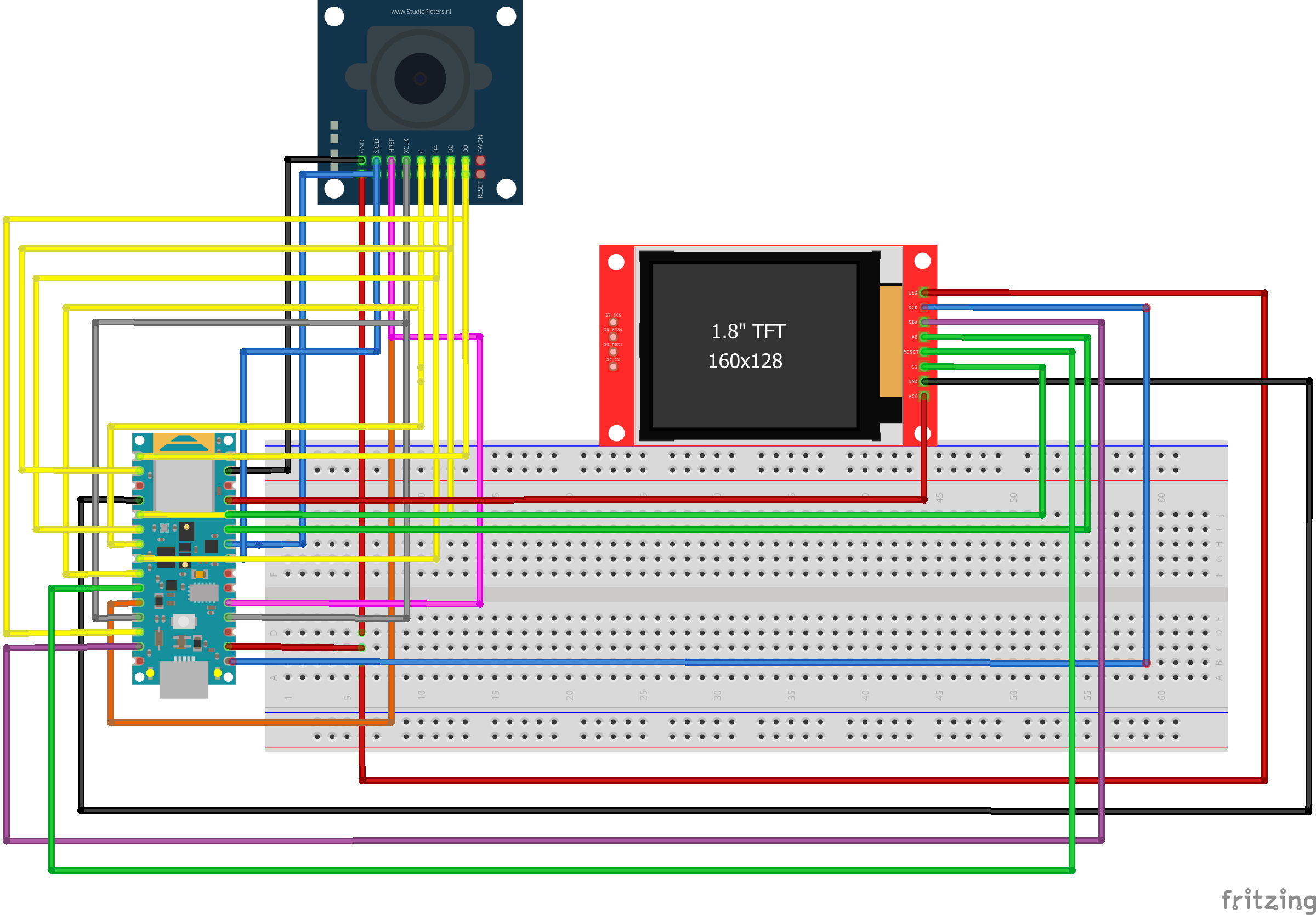


Comments