It's a golden time for Makers. With a handful of components and access to common maker tools, it’s now possible to build your own functioning cellphone that makes and receives calls and SMS texts, and even plays FM radio.
Adafruit’s Fona, a GSM/Phone module, allows makers to do lots of things on a cellphone network. Around the time the Fona was introduced, I had just discovered “DieselPunk” (like SteamPunk, only the era from roughly 1930s to the end of WWII) and I was inspired to make a cellphone in an imagined retrofuturestyle. Something fun and artsy that actually made you think about our relationship to tech and culture.
I started out just drawing sketches on napkins at the coffee shop. I'm no artist, but these little sketches helped me visualize what I wanted.
Early concept sketch for DieselPunk Cellphone
Most of the concepts I came up with were way too advanced for me. I would have to improve my 3D printing skills (from rank beginner) to make the sketch shown above.
After a lot of thought and some prototypes, I inched closer to the final concept:
DieselPunk Wood Case Concept 1 (of many!)
Kept refining things and finally made a critical design decision. Up until late 2016, I had kept trying to "re-invent the wheel", create custom features and parts that already had available solutions. Gee, why not use off-the-self parts?
Finally, I settled on a case I could make that could fit all the off-the-shelf components.
DieselPunk Case - "Almost" Final Concept
There were still design constraints. I wanted this cellphone to have about the footprint of an iPhone 6, but of course, it would be thicker, about one inch. Another event that changed things was Adafruit released its Feather Fona board, in February 2016. This was a great improvement over what I was doing, making everything compact: processor, Fona module and battery charger on one board!
However, I had to change my design a bit to fit the Feather Fona in - the case had to be made wider and I had to move a cutout for the USB charging port, among other changes. Back to the "drawing board".
Finally, I had a case that achieved my goals, given some compromises for what I could do. Key learning: starting with the case is exactly the opposite of what you should do! I should have started with the components in the first place, getting them to work and then figuring out how to make a case for them.
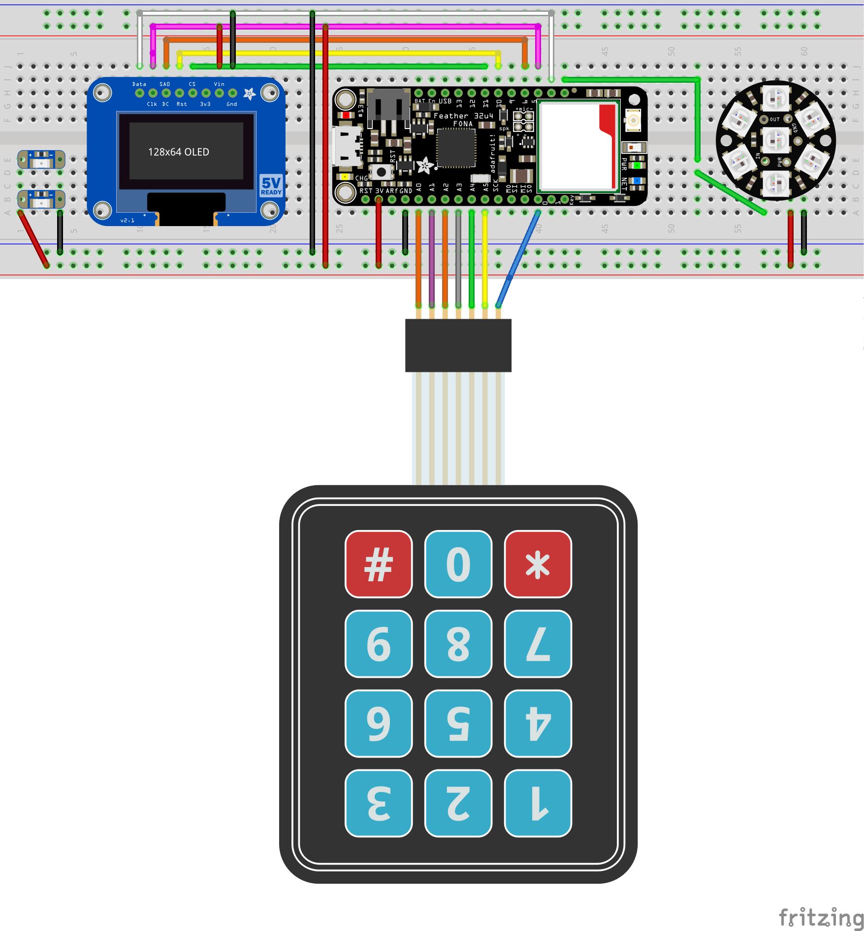
Download the Arduino sketch to the Feather Fona from the github repository. Assemble the components and make sure everything works
Connect components
Get 1/2 inch Walnut and Mill the case! Sand the case and remove holding tabs.
Milling the walnut case on ShopBot Buddy CNC
Laser-etch the front of the top case. You'll have to center the art on the OLED cutout for this.
Centering the laser for etching the art on the case
Cut out the speaker and microphone bezels on the laser cutter
Cutting the bezels on the laser
Epoxy threaded inserts into the top part of the case. You don't want the epoxy to seep into the inside threads.
Mask the insert before inserting into the case-top holes
Glue the speaker and microphone bezels in place with superglue.
Glue the back bezel "plaque" in place with superglue. Print out the Motorola Logo from downloaded artwork.
Prepare the circuit board. You will have to cut some traces and add jumpers due to required positioning of the OLED display and the Feather Fona.
Critical: you need to desolder the straight header pins on the dialpad and solder in right-angle headers instead. Otherwise, things won't fit. Align the OLED display into its cutout and hot-glue it down. Same with the dialpad. I fit some "vintage" grille fabric behind the grill bezel, friction-fit in place.
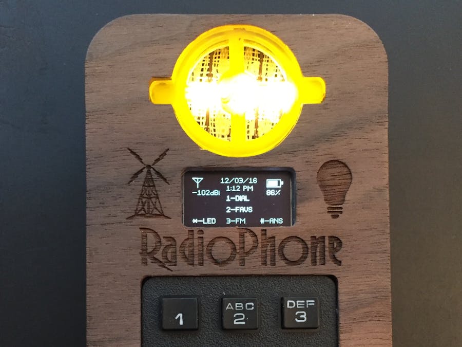
OLED and Dialpad glued in place
Solder jumper wires to the perma-proto board for the dialpad. Also solder the NeoPixel Jewel to the board
If you want to use the FM Radio, solder a 3.1 foot length of 22AWG wire to the back antenna pad. Because of the tiny speaker's range (~600-10kHz), speech sounds fine, but FM radio sounds bad, missing the highs. You will wrap the antenna around the dialpad and other components in the top of the case.
Optionally, you can solder Adafruit "LED Sequins" to a chunk of perma-proto board to backlight the microphone bezel. If you do that, remember to solder the Sequins to the perma-proto (just +V/GND) before mounting the board in place.
Solder the speaker and microphone to the Feather Fona, feeding the wires in through the top, adding solder on the bottom of the Feather Fona.
Connect the JST extension to the battery jack. Thread the battery/JST extension under where the speaker will sit. This extension connects to an on-off switch on the back case.
Test fit the Feather Fona onto the OLED pins. The 'USB' pin should be at pin 5 of the perma-proto.
Solder the Feather Fona in place. Cover soldered pins under the speaker with electrical tape to prevent shorts. Fit the speaker down into the speaker cutout and hot-glue in place.
Cut the extension to attach to the 12mm on-off switch on the back. Solder to the switch and attach the battery. Cover soldered pins with electrical tape to prevent shorts. Test the switch to make sure it works. Superglue the switch in place.


Comments
Please log in or sign up to comment.