


Hardware components | ||||||
 |
| × | 1 | |||
| × | 1 | ||||
| × | 1 | ||||
| × | 1 | ||||
 |
| × | 1 | |||
Software apps and online services | ||||||
| ||||||
Since many years ago I've had components waiting to be used for something more or less important. Thus the Hackster Junk Drawer Competition was a great opportunity to both use a few of those components as well as learn something new along the way, not forgetting to also have some fun! While I've published plenty of IoT & ML-projects before, this is my first project on Hackster.
This project is mainly targeting the Pop Culture Dream category in the competition, where the idea is to create the most innovative, relevant, and fun creation related to pop culture. After a bit deliberation, I decided that I wanted to include some lights and some type of "drums" - or other moving parts - to react to different sound frequencies captured through a microphone.
The video of course showcases the project, but pay attention to the lyrics as well 😀.
BuildI could've chosen between many different MCU's (Arduinos, Parallax P1/P2, Sony...) found in my drawers, but as I've recently mainly used the Particle Photon 2, I decided to use that as a base. Luckily I had two of them, which saved this project from complete failure, more on that later. As programming environment I used Visual Studio Code with the Particle Workbench extension.
When building, I decided to take a step-by-step approach, ensuring each component and library independently works, before adding them into the main device and program.
Microphone and FFT
First of all I needed to solder pins to the microphone breakout board, confirm that it worked, and find a FFT (Fast Fourier Transform) library. The FFT algorithm converts a signal from the time domain into the frequency domain, meaning one can create a device reacting differently depending on the frequency/frequencies captured. There are many Arduino-flavored FFT-libraries available, but the only one I got to work was EasyFFT. I tried another library as well, but trying to solve all the dependency errors led to hours of frustration.
All the main magic is controlled from the analyzeBuffer-function:
// --------------------------------------------------------------------------
// Analyze raw audio buffer to detect energy and optionally trigger servo
// --------------------------------------------------------------------------
void analyzeBuffer(uint8_t *buf, size_t bufSize) {
The microphone samples sound with a rate of 16 kHz (can be lowered). Depending on the amount of samples used for calculation, how many different frequencies to be calculated, processor speed, etc., the lag between sound and induced effect varies, which needs to be considered accordingly.
As I found a NeoPixel Ring with 12 leds, it felt most logical to use 12 frequency bins, from low bass to higher pitches, leading to a range from 375 Hz (3) to 4000 Hz (32).
// Select bins to cover a wide range of frequencies in pop music
size_t selectedBins[nr_of_bins] = {3, 5, 7, 9, 11, 14, 17, 20, 23, 26, 29, 32};
In addition I decided to use a Hamming window before running the FFT, this results in less frequence leakage between adjacent frequencies.
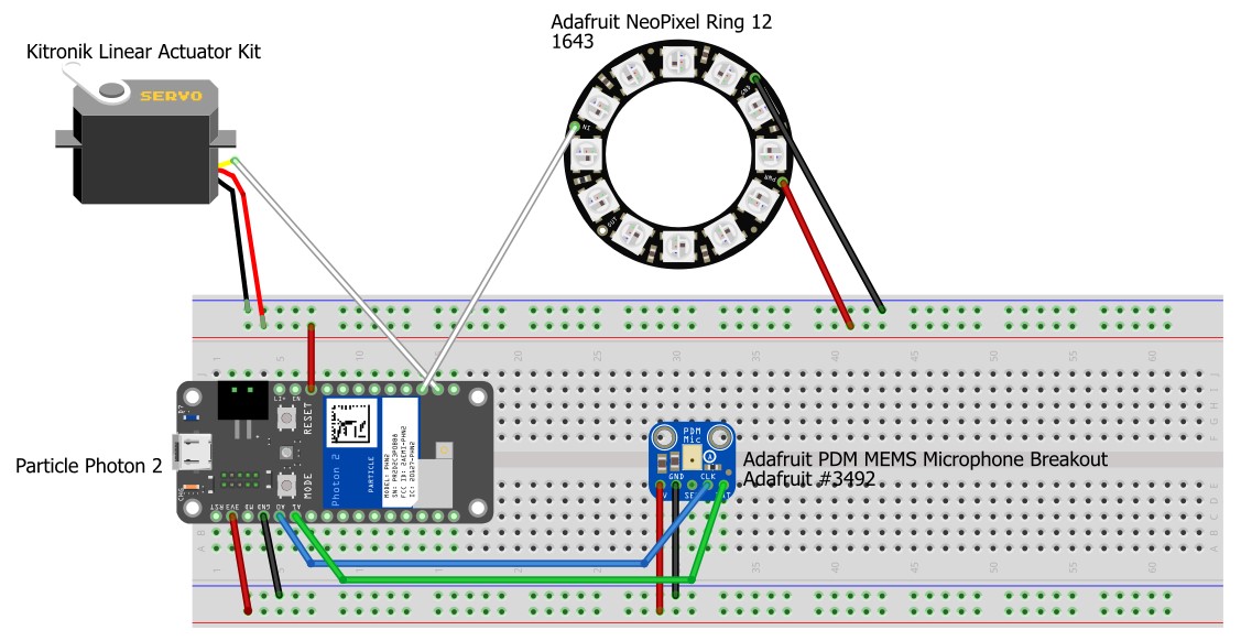
Microphone wiring:
-------------------
| Photon 2 | Mic   |
|----------|-------|
| 3V3      | VDD   |
| GND      | GND   |
| A0       | CLK   |
| A1       | DAT   |
--------------------
NeoPixel Ring and Color Interpolation
Getting the NeoPixel Ring to work was surprisingly easy as I found a Particle library ready to use as such. But just turning leds completely on and off according to measured frequencies was not that aesthetic, hence I needed to implement a color gradient function through interpolating between red for the first pixel (7 o'clock in the picture) and blue for the last one (6 o'clock in the picture).
The leds are at lowest 1 % brightness when only background sound is measured, but as soon as a threshold is reached, the brightness is changed according to the frequency amplitude.
Color interpolation code:
uint32_t interpolateColor(uint32_t color1, uint32_t color2, float fraction) {

  uint8_t r1 = (color1 >> 16) & 0xFF;
  uint8_t g1 = (color1 >> 8) & 0xFF;
  uint8_t b1 = color1 & 0xFF;

  uint8_t r2 = (color2 >> 16) & 0xFF;
  uint8_t g2 = (color2 >> 8) & 0xFF;
  uint8_t b2 = color2 & 0xFF;

  uint8_t r = r1 + fraction * (r2 - r1);
  uint8_t g = g1 + fraction * (g2 - g1);
  uint8_t b = b1 + fraction * (b2 - b1);

  return (r << 16) | (g << 8) | b;
}
Main led-control, setting brightness between 1% and 95%:
// Define base colors for the gradient
uint32_t colorStart = strip.Color(255, 0, 0);   // Red
uint32_t colorEnd = strip.Color(0, 0, 255);     // Blue

// Minimum brightness threshold
const float minBrightness = 0.01; // 1% brightness
// Update NeoPixel LEDs based on the magnitudes

for (size_t i = 0; i < nr_of_bins; i++) {
  size_t bin = selectedBins[i];
  float fraction = vReal[bin]; // Use the normalized magnitude as the fraction

  uint32_t color = interpolateColor(colorStart, colorEnd, (float)i / (nr_of_bins - 1)); // Fixed color for each LED
  uint8_t r = (color >> 16) & 0xFF;
  uint8_t g = (color >> 8) & 0xFF;
  uint8_t b = color & 0xFF;

  double_t maxBrightness = 0.95; // Maximum brightness is 95%

  // Adjust brightness based on the magnitude with a minimum threshold until 95%
  r = (uint8_t)(r * (fraction * (1.0 - minBrightness) + minBrightness) * maxBrightness);
  g = (uint8_t)(g * (fraction * (1.0 - minBrightness) + minBrightness) * maxBrightness);
  b = (uint8_t)(b * (fraction * (1.0 - minBrightness) + minBrightness) * maxBrightness);
  strip.setPixelColor(i, strip.Color(r, g, b));
NeoPixelRing wiring:
-----------------------
| Photon 2 | NeoPixel |
|----------|----------|
| VUSB(5V) | VDD      |
| GND      | GND      |
| D2(SPI1) | IN       |
-----------------------
Servo
As servo I used the Linear Actuator Kit which is handy when you don't need larger movements. The challenge with servos in general, are that they need a certain time to reach the wanted endpoint, and time is of course of essence when playing high-tempo music! This fact is also visible in the video, where it seems the servo can't always keep up with the rhytm.
I had actually planned to use two identical servos, but would've probably latest then needed a separate power source for them and the NeoPixel Ring. So I first tried to use a MAX98306 audio amplifier connected to a surface transducer to create some type of drum effect, but found out that it needed more power than was available. So, to not complicate this project further, I decided to use one servo only, but moving to the left or to the right, depending on two different frequencies.
"Drumming" code:
// Check if the bin magnitudes are over the threshold
if (vReal[2] > 300) {
  drum1();
}

if (vReal[10] > 300) {
  drum2();
}
Servo wiring:
-----------------------
| Photon 2 | Servo    |
|----------|----------|
| VUSB(5V) | VDD      |
| GND      | GND      |
| D1 (PWM) | Pulse    |
-----------------------
The picture below shows how the linear actuator is hitting one of the bells before returning to center. From a previous project I had 3D-printed a white TPU case for the servo motor itself. The case can be mounted on a standard 1/4” thread tripod screw.
3D-printed servo case:
Test Music Generation
To be able to film the final contraption I wanted some modern pop music, but for copyright issues I didn't want to use any existing songs. So, instead of playing an instrument and singing myself (which I can't), I decided to use Suno AI to generate music. The lyrics are targeted for this competition, which you'll probably notice when you watch the video.
The song is played from a laptop connected to an external Bluetooth speaker. The laptop, turned into portrait mode, is at the same time showing the lyrics on the screen.
Apart from uncooperating libraries, there hadn't been any major obstacles until this final stage, everything had worked both independently, as well as together for several days. Thus it was time to film everything, and as I couldn't use my laptop for powering the Photon 2 anymore, I connected it to a normal 5V power bank. Then nothing happened, checked with a power bank I've used earlier, nothing happened, connected to the laptop, nada... I suspect the power bank might've been the culprit and killed the Photon 2 as everything had worked earlier. I rechecked all wiring, but everything was as it should be, the only thing that changed was that I switched the USB-cable from my laptop to the power bank.
This could've been a disaster, but luckily I had a spare Photon 2, so after again rechecking everything, I flashed the program to finally start filming.
As always there are room for improvements, especially on the servo movement side. For a more permanent installation, I'd use better wires as well as design and 3D-print cases. A separate power source for the servo is probably also a must.
All in all, despite the final hickup, this was a fun project where I reached the goal, and along the way learned a lot!


Comments
Please log in or sign up to comment.