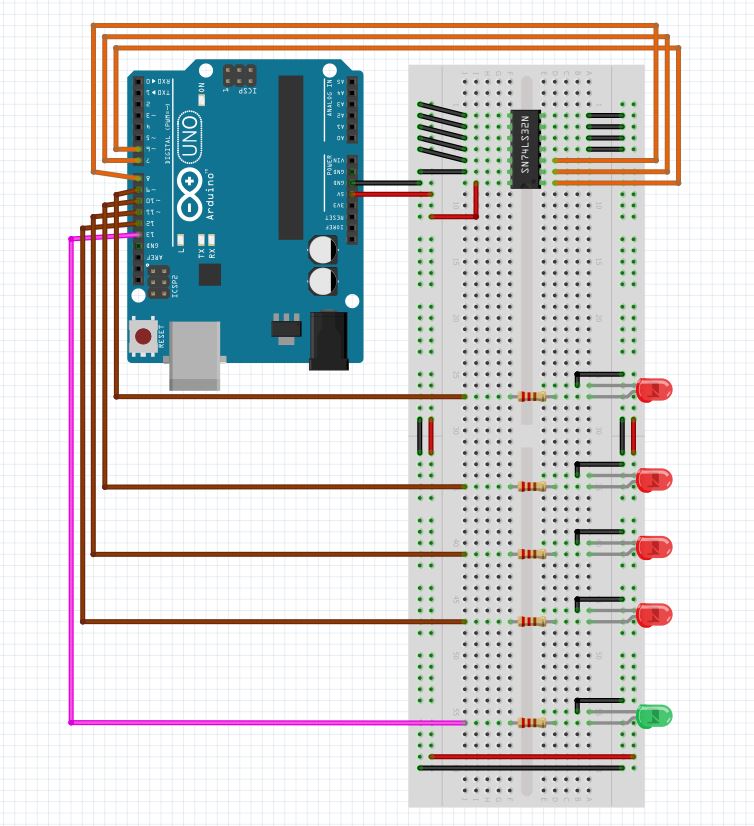
The main purpose of this project is to check logic gate IC, whether the IC is working properly or not. The checking of the IC will be done using Arduino UNO. The main IC that are going to be checked are OR (7432), AND (7408), NAND (7400), EXOR (7486) and EXNOR (747266).
Working PrincipleIn this project Arduino, LED lights, resistors etc were used.
ARDUINOArduino is a single-board microcontroller meant to make the application more accessible which are interactive objects and its surroundings. The hardware features with an open-source hardware board designed around an 8-bit Atmel AVR microcontroller or a 32-bit Atmel ARM. Current models consists a USB interface, 6 analog input pins and 14 digital I/O pins that allows the user to attach various extension boards.
The Arduino Uno board is a microcontroller based on the ATmega328. It has 14 digital input/output pins in which 6 can be used as PWM outputs, a 16 MHz ceramic resonator, an ICSP header, a USB connection, 6 analog inputs, a power jack and a reset button. The code of the project were install in the Arduino. The arduino sends signals to LED lights when necessary and passes the signals. The connection is done according to the above diagram.
LED LIGHTS: A light-emitting diode is a two-lead semiconductor light source. It is a p–n junction diode that emits light when activated. When a suitable voltage is applied to the leads, electrons are able to recombine with electron holes within the device, releasing energy in the form of photons. In our project, we used 4 LED for checking logic gates. If the lights are on according to the respective truth table then the IC is working. However, if the IC is damaged or different IC which is not in our IC list then the single output LED will turn ON. The connection is done according to the connection diagram.
RESISTORSA resistor is a passive two-terminal electrical component that implements electrical resistance as a circuit element. In electronic circuits, resistors are used to reduce current flow, adjust signal levels, to divide voltages, bias active elements, and terminate transmission lines, among other uses. In IC tester, the resisters are protecting LED. The connection is done according to the connection diagram.
Performance AnalysisAfter constructing the project we test the project by some ICs. The ICs were the specific IC mentioned in the project, one damaged IC (7400) and a 7404 IC. When we connected the ICs 7432, 7408, 7400, 7486 and 747266 to the project one by one, we found that the LED lights are working according to the respective truth table. The single output LED light will remain off in this case. Thus the project is working. When we connected the IC 7400 which was damaged to the project, we found that the single LED output light is on. This means the IC is damaged one. Hence, the project is working. When we connected the IC 7404, we found that the single LED output light is on. This means the IC is damaged one. Since, the IC is not in list of our project ICs, it seems the IC is damaged. Hence, the project is working.
Error analysis• The project can deal with the five specific models. Error occurs when any other IC is used. So, if any IC of other model are used then the project will treat it as a damaged one.
• The project can check only one gate. Usually if a gate works, then the IC works. However, in some cases that may not be happen.
ConclusionIn this project we are only able to test only 5 logic gate IC of the 74** series, because we tried this project in a small scale. To test more IC’s we can use Arduino MEGA or Raspberry Pi, because more number of pins are required and the project will become more expensive.
References• http://electrofriends.com/projects/microcontrollers/digital-ic-tester/
• http://www.computernerdkev.heliohost.org/ictesters/index.htm


_ztBMuBhMHo.jpg?auto=compress%2Cformat&w=48&h=48&fit=fill&bg=ffffff)


Comments
Please log in or sign up to comment.