


Hardware components | ||||||
| × | 1 | ||||
| × | 1 | ||||
| × | 1 | ||||
 |
| × | 1 | |||
 |
| × | 1 | |||
 |
| × | 3 | |||
 |
| × | 2 | |||
Software apps and online services | ||||||
 |
| |||||
Hand tools and fabrication machines | ||||||
 |
| |||||
 |
| |||||
Have you ever heard of the Sick Building Syndrome (SBS)? This umbrella term unites numerous non-specific illness symptoms from spending time indoors. This phenomenon has been recognised since early 1980s, and now there is a rich collection of papers linking SBS to ventilation rates and indoor carbon dioxide (CO2) concentration. We know that chronic exposure to more than 800 parts-per-million (ppm) of CO2 can reduce our wellbeing and even provoke chronic disease. [1]
In 2019, another health hazard joined the list. SARS-CoV-2 is an airborne virus, and its viral particles can survive and remain infectious for up to ten times longer in poorly ventilated spaces [2]. With omicron on the rise [3], it is the time to follow the Slovenian kindergartens, who obviously prioritized air quality over the thermal comfort of their visitors [4]. Although, perhaps, we can be a little less radical with keeping the windows open when it snows...
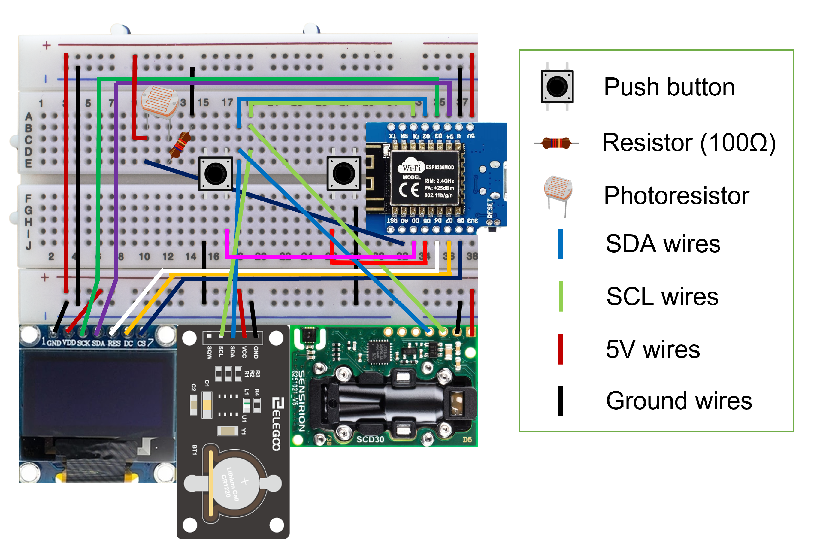
With this noble thought in mind, I was enrolled in a "Build Your Own CO2 Sensor" workshop. With a Grove shield, an SCD30, an eight-segment display, and a push button, we embarked on a journey to create the ultimate Arduino project. Following instructions inspired by a niche French website, we assembled a device capable of motivating the upkeep of high air quality inside any lecture hall.
As you may have noticed, the resulting prototype had many tangling wires and took a lot of space, which drastically reduced its EDC potential. So, equipped with a soldering iron and everlasting procrastinating issues, I decided to ameliorate the situation and make a pocket-sized version of this device.
Glue gun >> 3D printerOne does not simply revitalize an old project without adding a few features. For instance, I dislike 8-segment displays. Despite their "Retro" appearance, they always feel severely limiting for my creative genius. Gladly, I had an OLED display collecting dust in a corner, as well as a Real-Time Clock module. After swapping Arduino Uno with a ESP8266-based development board to exploit its WiFi functionality, I began soldering all the pieces together.
Spoiler: I could've stayed with Arduino.
After a few hours of trying to fit everything on a generic 4x6 PCB, the screen finally powered up. Some of the connections felt a little flimsy and easy to break, so (in absence of a better option), a milestone decision was made: soak it all in the hot glue. And, voila - the pocket CO2 monitor and weather station is now ready to go.
Dim the lightsSomehow there is no simple tutorial showing how to control the brightness of a '0.96 OLED screen. But then, this never stopped anyone!
Tweaking contrast and precharge allows sufficient brightness adjustments. Solder A0 to a photoresistor in sequence with 2 parallel 220 Ohm resistors, and now you can adapt the screen brightness in response to the ambient light. Magic!
Maximum values: contrast = 255 precharge = 34
1. Every temperature sensor has an intrinsic source of error: it heats up. SCD30 is no exception, and it easily gains 2-3°C after within first minutes of powering-up. Normally, it is not an issue, because the sensor is designed for for continuous work: a single-time temperature offset completely resolves the problem. However, with the pocket format, the offset depends on how long the sensor has been running for. Hence the custom temperature offset function, which allows you to add an offset value based on temperature registered at start-up.
This solution is far from perfect - please suggest better options in the comments!
2. SCD30 relies on a reference value to calculate the ambient CO2 concentration. And since the automatic calibration is a mess, it is easiest to utilise the reference value of 417 ppm and perform forced re-calibration outdoors. The device has to be running for at least 2 minutes in stable CO2 conditions, which is why the script does not offer this option straightaway. Once calibrated, the device stores the new reference value in non-volatile memory of the SCD30, which means it stays there even once you have cut the power. Neat!
Shortly after programing the breadboard prototype, I noticed my gadget freezing. Sometimes after a few minutes, oftentimes after a few seconds. This behaviour seemed random, and it took a while to find and eliminate the culprit.
The first problem came in the form of a single "stock" library provided by my Elegoo starter kit. Their "DS1307.h" required an instance of a class containing multiple String objects to read and store the Real Time Clock module output. In simple words - it used way too much memory for a fairly simple task. Gladly, swapping the library solved the freezing issue for good.
Furthermore, every now and then the RTC randomly outputs 165 for time and/or date values. I couldn't find the source of this peculiarity, so instead my script skips a frame if any of the values is suddenly 165. Engineering at its finest, I know.
IoT not!When I picked an ESP8266-based board, I wanted to add two Internet-of-Things functions:
- Log/share data using WiFi (e.g. via a Telegram bot);
- Display outdoor weather (like Martin Smaha).
An attempt to add OpenWeather API wasn't as successful as envisioned. Well, it actually fried up my development board! The poor D1 eventually stopped showing any signs of life and had to be replaced. After a closer look, I realized that a single WiFi.begin(); line was enough to screw with the ESP's brains, resulting in a drastically slower screen refresh rate (sometimes even skipping a few seconds).
Since I have a different WiFi-based project with the identical "brain" running just fine, I suspect there must be a problem with overloading the volatile memory (again!). Quite a shame, I could've used my Logan Nano and spared an OLED.
RemarksHere are some bonus observations to help fellow hobbyists:
- The built-in LED of Wemos D1 mini is connected to one of the digital pins. My clone had it at D4, so it flickers every time the screen is updated. Fun!
- The D0 pin of my board had no input-pullup capacity, so the final PCB layout differs from the breadboard one. Always check documentation!
- DuPont female connectors + PCB = magically simple component replacement. Especially if you covered it all in hot glue. Really.
Let me know what you think in the comments, feedback always makes me happy!


_3u05Tpwasz.png?auto=compress%2Cformat&w=40&h=40&fit=fillmax&bg=fff&dpr=2)


Comments
Please log in or sign up to comment.