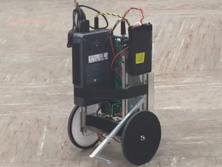
In this project, a custom Segway robot is used which is operated using NI myRio platform. The platform also has a Texas Instruments' MSP430 chip mounted on it. The goal of this project is to make the robot balance on its 2 wheels while the camera hooked up on the robot looks for commands in the forms of colors. Depending on the color the webcam sees, the robot executes different trajectories.
Control of SegBot and StabilizationThe robot is stabilized through a state feedback controller. The states for this control include the wheel velocity, the robot's tilt, and the tilt rate. From the outputted torque, a PWM voltage is sent to the motors driving the wheels. When the reference states are given as 0, it implies that a fixed upright position of the robot is the desired pose.
Since we have 2 wheels which can be independently controlled, it is possible to change the orientation of the segbot (e.g. spin it about its axis) while maintaining the upright pose. This is done by finding the difference in the wheel encoder readings. If a rotation is desired, a change in the desired encoder difference is input to a PI controller which outputs a differing torque to each wheel.
In order to estimate the tilt of the robot, a Kalman filter is used. The Kalman filter fuses a slow to respond, yet accurate tilt measurement from an accelerometer with a responsive but noisy rotation rate given out by a gyroscope. Using both of these signals, the Kalman filter gives an accurate and responsive signal that can be used for the state feedback control.
The robot's moving speed is calculated using the wheel encoder data. A PI controller uses the desired speed as reference input and the robot's current moving speed to determine what change in tilt angle achieves the desired speed. This desired tilt angle acts as reference input to the main state feedback control law discussed above.
Color Processing and State Machine LogicImages are taken from the webcam and processed using the Image Processing tools of LabView. In order to build a color detection based state machine, what color an image contains must be determined and as well as what the largest blob size corresponding to that color is. Looping through four HSV color definitions (pink, green, orange and no color) defined in the LabView code, the camera detects which color is in view and calculates the number of pixels in the largest blob of that color. The calculated number of pixels are then compared with a given threshold value to ensure that it is a correct sighting and not some error/noise in the image processing. When a correct sighting is found, it is used as an input for the state machine that determines the desired robot trajectory.
The color based state machine works as follows. When a color is detected by camera, the Segbot executes a trajectory corresponding to that color once and stops when it has completed it. It then waits for another color all the while holding it's upright position.
In our case, a figure 8 is executed when the color green is spotted by the camera and when it spots an orange color, the robot completes a circle. The robot is programmed to dislike pink and so, when pink is spotted, the robot turns away by 90 degrees from that color. Finally, if no color is seen, the robot hold it's upright position.
Communicating with MSP430The MSP430 is used to control LED turn signals on the robot itself. When the robot turns in the left direction or the right, an LED for that direction will blink until the turn is finished. The myRio communicates with the MSP430 through an I2C protocol which is used to send and receive 16-bit integers. The data that is sent from myRio to MSP430 is the desired robot's turn angle. Increasing turn angles result in the right turn signal being activated while decreasing turn angles activate the left.


Comments
Please log in or sign up to comment.