In this tutorial, I will be using a 16x2 lcd screen and GPIO pins 25, 24, 23, 17, 18, and 22. However any size screen i.e. 16x4 would also work as long as it's a character lcd screen and you can find the correct RAM addresses in your datasheet, and you can use any GPIO pins.
If you have a different size screen, you can chage the hieght by adding to this code:
LCD_LINE_1 = 0x80 # LCD RAM address for the 1st line
LCD_LINE_2 = 0xC0 # LCD RAM address for the 2nd line
i.e. for a 16x4 it would be:
LCD_LINE_1 = 0x80 # LCD RAM address for the 1st line
LCD_LINE_2 = 0xC0 # LCD RAM address for the 2nd line
LCD_LINE_3 = 0x94 # LCD RAM address for the 3st line
LCD_LINE_4 = 0xD4 # LCD RAM address for the 4nd line
And to change the width simply change the last number (16 in this case) to the width of your screen:
lcd.init(25,24,23,17,18,22,16)
If you use different GPIO pins change the first 6 numbers of the code above. Those numbers are as follows: 1st number: RS (lcd pin 4), 2nd number: E (lcd pin 6), 3rd number: D4 (lcd pin 11), 4th number: D5 (lcd pin 12), 5th number: D6 (lcd pin 13), 6th number: D7 (lcd pin 14). the full pinout is in the wiring section.
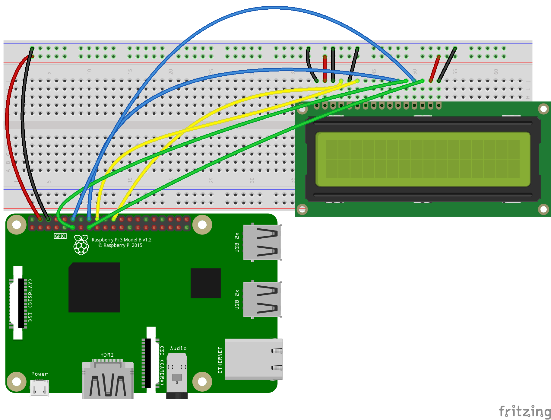
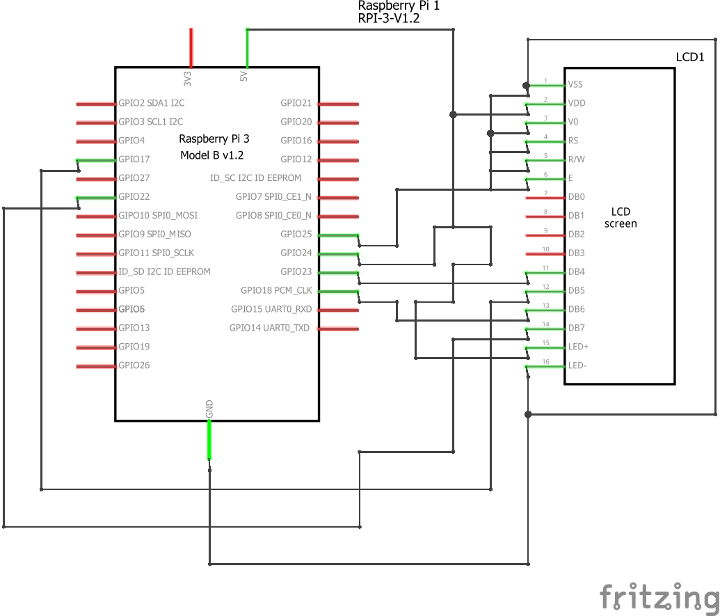
Wiring:My current setup has:
lcd pin 1 > GND
lcd pin 2 > 5V
lcd pin 3 > GND
lcd pin 4 > GPIO 25
lcd pin 5 > GND
lcd pin 6 > GPIO 24
lcd pin 7-10 > nothing
lcd pin 11 > GPIO 23
lcd pin 12 > GPIO 17
lcd pin 13 > GPIO 18
lcd pin 14 > GPIO 22
lcd pin 15 > 5V
lcd pin 16 > GND
~
~
However, as mentioned earlier, you can use any pins. The lcd pinout is:
1. Ground
2. VCC (Usually +5V)
3. Contrast adjustment (VO)
4. Register Select (RS). {RS=0: Command, RS=1: Data}
5. Read/Write (R/W). {R/W=0: Write, R/W=1: Read}
6. Enable
7. Bit 0 (Not required in 4-bit operation)
8. Bit 1 (Not required in 4-bit operation)
9. Bit 2 (Not required in 4-bit operation)
10. Bit 3 (Not required in 4-bit operation)
11. Bit 4
12. Bit 5
13. Bit 6
14. Bit 7
15. LED Backlight Anode (+)
16. LED Backlight Cathode (-)
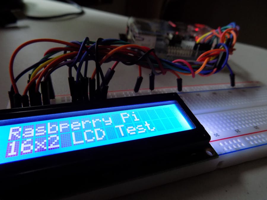
Here's my setutp. It's hard to see where the wires go though, so go to the shematics section for better pictures.
Before we start programming we need to install a library I created here. To do this, we must first go there and download the library as a zip folder. Then, extract it to wherever you want using the archive manager. Now we have to open the terminal to move the file to the correct location. Let's use the mv command for this. Just type or copy the following into your terminal replacing /home/pi/Wherever_You_Extracted_Your_Folder_To/lcd_lib-master/lcdlib.py
with the path to the lcdlib.py file.
sudo mv -v /home/pi/Wherever_You_Extracted_Your_Folder_To/lcd_lib-master/lcdlib.py /usr/lib/python3.4
If you use a different virsion of python i.e. 2.7, replace the python3.4 to whatever version you use.
Code:
The code is rather easy. At the beginning of each script, you must import the library by typing: import lcdlib as lcd
. Then, remember to define your RAM addresses, in my case:
LCD_LINE_1 = 0x80
LCD_LINE_2 = 0xC0
Now the last bit of initialization is the lcd.init()
function, which we talked about earlier.
Now you can use the lcd.string()
to display your text.


Comments
Please log in or sign up to comment.