

Hardware components | ||||||
_ztBMuBhMHo.jpg?auto=compress%2Cformat&w=48&h=48&fit=fill&bg=ffffff) |
| × | 1 | |||
 |
| × | 2 | |||
 |
| × | 1 | |||
 |
| × | 1 | |||
 |
| × | 1 | |||
| × | 1 | ||||
| × | 1 | ||||
Software apps and online services | ||||||
 |
| |||||
 |
| |||||
 |
| |||||
 |
| |||||
| ||||||
Main objective on why the project was created is to study the mouse population in a certain area and how the humidity and temperature is affecting their numbers. Although the study is not covered on this project our goal is to build a smart mouse trap that require less human intervention compare to the conventional mouse trap. To achieve this, the device shall be equipped with sensors that will detect incoming mouse and once caught will send a notification thru email or SMS to alert a person eliminating the need to periodically check the mouse trap. Record of mouse count will then be push to a cloud database for further analysis should the data accumulated more enough. A temperature and humidity sensor was also added to register the reading at the time mouse has been captured.
2. Project OverviewAssemble the arduino, antenna and unashield together and connect to your laptop.
To activate the UnaShield and get access to Sigfox Backend, please refer to https://github.com/UnaBiz/unabiz-arduino/wiki/Activation or follow the below instruction.
1. Go to https://backend.sigfox.com/activate/Unabiz and select your country
2. Using a mobile phone, scan the QR code on your UnaShield to retrieve the Sigfox Device ID and PAC (Porting Authorization Code)
3. Enter the Sigfox Device ID and PAC into the activation screen
4. Enter your personal particulars to register for a Sigfox Backend account
5. Check your email account for the activation email. Click the link inside.
6. Type your password twice. Please use a secure password with 8 or more characters, containing at least one uppercase letter, one lowercase letter, one digit and one symbol e.g. !@#$^
7. Once registered and activated, you may login to http://backend.sigfox.com, the Sigfox Backend Portal.
8. When you have successfully sent a message from the UnaShield to the Sigfox basestation, the network indicator at the left of the screen should turn green. To see the UnaShield messages received by Sigfox, click on your device ID shown in the centre of the screen.
9. You will see a list of messages received by the Sigfox network from your UnaShield device. Click a message to see the details.
10. You may also configure the Server Callback that Sigfox will call to pass any received messages. This is configured under "Device Type". Click your device type and select "Callbacks". This document explains more details about configuring the callback, including downlinks: https://github.com/UnaBiz/sigfox-gcloud/blob/master/README.md
1. Install the latest Arduino Integrated Development Environment (IDE) from https://www.arduino.cc/en/Main/Software
2. Browse to https://github.com/UnaBiz/unabiz-arduino
3. Click Clone Or Download then Download ZIP
4. Launch the Arduino integrated development environment. Click Sketch → Include Library → Add.ZIP Library
5. Select the downloaded zip file. After the installation you should see unabiz-arduino or unabiz-arduino-master when you click File → Examples.
Upload the program on the arduino using the code attached. Below shows the program flowchart.
Below figure shows our workflow for connecting to AWS.
1. PREPARE AMAZON WEB SERVICES ACCOUNT
Step 1: Go to https://aws.amazon.com/and create your free trial account.
Step 2: Click on “Support” in the top right corner, then “Support Center”.
Copy your account number located in the upper right corner.
2. CONFIGURE SIGFOX CALLBACKS
Step 1: Connect and login to the Sigfox backend at https://backend.sigfox.com
username: xxxxxxxxx
password: xx@ttttt
Step 2: Select “Device Type” tab on the top menu
Step 3: Select or type in your device type from the “Name” column and click on it
Step 4: Click on “Callbacks” on the left side menu.
Step 5: Click on “New” on the top right corner
Step 6: Choose AWS IoT as a new callback
Step 7: Copy the “External Id” given to you in your clipboard
Step 8: Click on “Launch Stack”
Step 9: You have been redirected to the AWS Cloud Formation console, click on “Next”
Step 10: Enter the following inputs:
• Stack name: choose a meaningful name
• AWSAccountId: paste the Id you copied earlier
• External Id: paste the Id off of your Sigfox backend
• Region: enter the region name that is located your URL
• Topic name: choose the topic name you wish to send data to
Click on “Next”.
Step 11: You can customize the next screen optionally, or click “Next”, then the acknowledgment box and “Create”. Then, press F5 to refresh the screen
An error will appear:
Open another window, go into “Services” in the top left corner and type in “IAM”. Click on “Roles” on the left side menu and click on “Create New Role”.
Add a name for your new role. Select “AWS Lambda” as a Role Type
Attach the following policies:
Press “Next” and Create Role.
You have now created a special IAM role that will allow your function to use the AWS IoT service and write into a DynamoDB
Important: Go back to Step 11. Click “Next”, then the acknowledgment box and “Create”. Then, press F5 to refresh the screen.
Step 12: Wait for the stack creation completion. Tick the Stack Name and Click on “Outputs”. Copy the value of “ARNRole”, “Region” and “Topic”.
Step 13: Go back to the Sigfox backend and fill in the following fields:
• ARN Role: paste the value you copied in AWS Cloud Formation
• Topic: paste the value you copied earlier
• Region: choose the region from your Cloud Formation stack
• Custom payload config:
int1::uint:16:little-endian int2::uint:16:little-endian int3::uint:16:little-endian int4::int:16:little-endian int5::int:16:little-endian int6::int:16:little-endian
• Json Body:
{
"device" : "{device}",
"time" : "{time}",
"snr": "{snr}",
"station":"{station}",
"latitude":"{lat}",
"longitude":"{lng}",
"rssi":"{rssi}",
"avgSnr":"{avgSnr}",
"seqNumber":"{seqNumber}",
"data": "{data}"
}
3. CHECK THAT MESSAGES HAVE BEEN RECEIVED IN AWS IOT
Step 1: To check if your callback went through, go into “Device” tab, enter your device name.
Step 2: Click on “Messages” and check if there is a green arrow on the right side of your callback. It is a confirmation that your callback went through without issues.
Step 3: Go back into AWS IoT.
Step 4: Click on AWS IoT, then “Get started”.
Step 5: On the left side menu, you will find “Test”, click on it.
Step 6: Enter the subscription topic you previously chose in your Sigfoxcallback. Click on “Subscribe to topic”.
Step 7: You will see your undecoded message and the region must be Singapore
4.CREATE A LAMBDA FUNCTION TO PARSE THE PAYLOAD
In this section, you will create a Lambda function that will decode the payload and push it in a DynamoDB database.
Step 1: You have now created a special IAM role that will allow your function to use the AWS IoT service and write into a DynamoDB.
Step 2: Go into your account tab in the upper right corner, click on “My Security Credentials”, then click on “Access Keys” and “Create a new access key”.
Step 3: Save your access key and secret key in a safe place. You will need them in the next step.
Step 4: You will now need to compute your IoT endpoint. To do so, you will need to download the Command Line Interface corresponding to your running OS. Follow the option that suits you best.
Option A: if you have pip (a package manager for Python), follow the steps at: http://docs.aws.amazon.com/cli/latest/userguide/installing.html
Option B: if you don’t have pip, following the steps at:
• For Linux, Unix, Mac OS: http://docs.aws.amazon.com/cli/latest/userguide/awscli-installbundle.html
• For Windows: http://docs.aws.amazon.com/
Step 5: Now that your AWS Command Line Interface is set up, go into your console/terminal and type in: aws configure
Step 6: Your console will ask you for your access key. Add it and press enter.
Step 7: Your console will then ask you for your Secret Access Key. Add it and press enter.
Step 8: Your console will then ask you for your Region. Add it and press enter. Output format: Text
Step 9: Type in the following: aws iot describe-endpoint
Step 10: Copy your AWS IoT endpoint.
Step 11: Go into “Services” at the top right and search for “AWS Lambda”.
Step 12: Go into “Functions” and “Create a Lambda function”. Type “python” under Blueprints and click search. Choose “hello-world-python”.
Step 13: Set role as “Choose an existing role”, choose the IAM role name you’ve created previously.
Step 14: In the basic settings, set your timeout to 5 min.
Step 15: Paste the following into the Lambda function code and update the “device id”.
from __future__ import print_function
import json
import boto3
import time
import datetime as dt
print('Loading function')

dynamodb_client = boto3.client('dynamodb')

table_name = '1c886d'

defgetFriendlyDate(epochString):
fts = dt.datetime.fromtimestamp(float(epochString))
 adjusted = fts + dt.timedelta(hours=8)
 fd2 = adjusted.strftime("%Y/%m/%d %H:%M:%S")
 return fd2

deffindChar(bStr):
chrs = '0abcdefghijklmnopqrstuvwxyz0123456789'
 return chrs[int(bStr, 2)]

defsfDecode(sfRaw):
disp = sfRaw.strip()
 #print disp, len(disp)

varDct = {}
 for j in range(8, 25, 8):
tempStr = disp[j-8:j+1]

# decode name
nameStr = tempStr[2] + tempStr[3] + tempStr[0] + tempStr[1]
binStr = ''
for k in nameStr:
binRep = bin(int(k, 16))[2:]
binRep = '0'* (4-len(binRep)) + binRep
binStr += binRep

vName = findChar(binStr[1:6]) + findChar(binStr[6:11]) + findChar(binStr[11:])

# decode value (integer and float values only)
valStr = tempStr[6] + tempStr[7] + tempStr[4] + tempStr[5]
val = float(int(valStr, 16))/10
varDct[vName] = val

    return varDct

deflambda_handler(event, context):
 #print("Received event: " + json.du)mps(event, indent=2))
 x = getFriendlyDate(str(event['time']))
 print("value1 = " + x)

sfData = str(event['data'])
 print("value2 = " + sfData)

sfDict = sfDecode(sfData)

 item = { 'device': {'S': event['device']}, 'data': {'S': event['data']}, 'time': {'S': x} }
 print (type(item))
 for i in sfDict:
  item[i] = {'N': str(sfDict[i])}
dynamodb_client.put_item(TableName=table_name, Item=item)

return event['data'] # Echo back the first key value
#raise Exception('Something went wrong')
Step 16: Click on “Create”
Step 17: Now click on your function. Click on “Designer” tab, then “Add a trigger”
Step 18: Choose “AWS IoT” as an input.
Step 19: Choose “Custom IoT rule” as IoT Type.
Step 20: Add a rule name. Enter the following SQL statement and click on “Submit”.
SELECT * FROM 'your_topic'
Make sure to change your_topic with the topic you entered in your callback in the Sigfox backend.
Step 21: Click “Save”
Step 22: Click “Test”
5.CONFIGURE THE TEST EVENTS
{
"device": "1C888F",
"time": "1509344810",
"snr": "12.60",
"station": "2B0A",
"latitude": "1.0",
"longitude": "104.0",
"rssi": "-131.00",
"avgSnr": "41.28",
"seqNumber": "423",
"data": "fd0df6ffb051be00ad229402"
}
6. PUSH DATA INTO DYNAMODB
Step 1: Go to services and click on “DynamoDB”. Click on “Create table”.
Step 2: Add your “deviceId” as a Table name.
Step 3: Add ‘deviceid’ as a primary key and ‘time’ as a sort key. Click on “Create”.
Step 4: Once you have created your table, click on it and go into the items Tab.
Step 5: You should be seeing the parsed payload coming in.
7. CHECK THE RULES IN AWS IOT
Step 1: Go to AWS IoT and click on “Act”. Click on the Rule that you have created.
Step 2: Ensure that the Trigger is created
8.LAMBDA FUNCTION TO CREATE EMAIL AND SMS NOTIFICATION
Follow the previous instruction and use the code below for notification function.
console.log('Loading function');
var AWS = require('aws-sdk');
AWS.config.region = 'ap-southeast-1';
exports.handler = function(event, context) {
console.log("\n\nLoading handler\n\n");
var sns = new AWS.SNS();
sns.publish({
Message: 'Mouse Trapped in the Cage!!',
TopicArn: 'arn:aws:sns:ap-southeast-1:158643732830:SNSTopic'
}, function(err, data) {
if (err) {
console.log(err.stack);
return;
}
console.log('push sent');
console.log(data);
context.done(null, 'Function Finished!');
});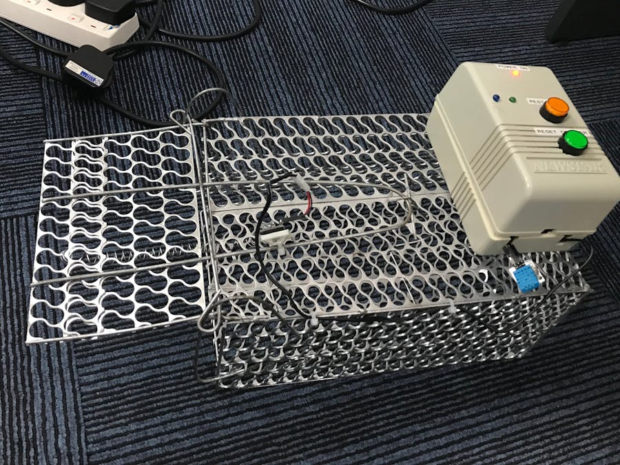
};I actually use recycled casing good enough to house the assembly. It is important to provide a cutout for the antenna and DHT11 sensor so that it will be outside of the casing.
Connect the tilt sensor on the mouse trap door using a cable tie. Tilt Sensor must be adjusted properly in order to avoid giving false signal to the controller.
Sigfox is very practical to the project not only because it consumes low power but also the IoT device can be deployed to an area where internet connection is not possible.
Although the instructions is very detailed, I will try to improve it and add some video instruction to make it less boring to follow. :-)


Comments
Please log in or sign up to comment.