


Hardware components | ||||||
_ztBMuBhMHo.jpg?auto=compress%2Cformat&w=48&h=48&fit=fill&bg=ffffff) |
| × | 1 | |||
 |
| × | 2 | |||
| × | 2 | ||||
| × | 1 | ||||
Software apps and online services | ||||||
 |
| |||||
Hand tools and fabrication machines | ||||||
 |
| |||||
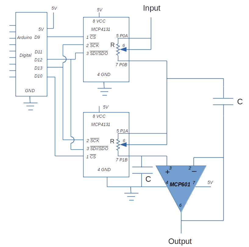
This project shows how a MCP4131 IC is controlled by an Arduino to implement a variable cutoff frequency filter. A Sallen Key filter is used with two MCP4131 digitally controlled potentiometers in the circuit. Using an Arduino to adjust these resistors varies the cutoff frequency of the filter.
Sallen Key FilterThe Sallen Key Filter is a second order active filter topology. A general circuit diagram below:
The values of R and C do not necessarily have to be the same but choosing them as such simplifies the design
For a detailed description of how the circuit works, refer to the Wikipedia article:
https://en.wikipedia.org/wiki/Sallen-Key_topology
The cutoff frequency (in the case R and C are equal) is given by the formula:
A brief description of the circuit:
- Sallen Key topology is implemented using the MCP4131 as the two resistances in the circuit
- The Arduino communicates with the MCP 4131 via the SPI bus
- D11 to D13 on the Arduino are configured as the SPI communication bus
- D10 and D9 are used as a Chip Select signal. This allows resistance of the MCP4131 to be set separately to different values. This is configurable in the Arduino sketch by the user
- The MCP4131 is set in the rheostat configuration with the wiper shorted to one of the output legs
- The resistance varies nominally from 0 ohms to 10K ohms
- For this experiment Capacitor C is set to 0.1 microF
- A MCP601 single rail power supply operational amplifier is used in the circuit. This can be substituted with other similar IC’s
The MCP family of integrated circuits are manufactured by Microchip and represent a range of digitally controlled potentiometers. The family of devices support 7-bit and 8-bit resistor networks using an SPI interface to control resistance.
A block diagram from the MCP data sheet:
The device can be used as two terminal variable resistor or a three terminal potentiomenter.
Control of the wiper position and hence the resistance is determined by the three digital inputs:
- Device is selected by taking CS low.
- Using a SPI serial interface (10 MHz, modes 0, 0 & 1, 1), high-speed Read/Writes are written to potentiometer registers. SCK synchronizes the clock between devices
- The wiper moves to the position determined by the value written to the register.
- The wiper has 128 (in the case of MCP4131) possible positions (0 – 128), allowing for incremental steps of about 0.8% of the total resistance.
- The current wiper position can be read from the MCP4131 via the SPI interface
Complete specifications for the MCP4131can be found at the Microchip website.
https://www.microchip.com/en-us/product/MCP4131
https://ww1.microchip.com/downloads/en/DeviceDoc/22060b.pdf
SPI InterfaceThere are multiple articles on the internet regarding the SPI interface. There is a standard library available for the Arduino to communicate via the SPI protocol.
The Arduino pin assignments for this project shown below:
There is a standard library available for the Arduino that allows control of the MCP4131. Use the Tools→Manage Libraries… command to bring up the library manager window.
Search for MCP4131 and install the library to your IDE environment.
In order for the library to work correctly with the Arduino sketch in this project, a small correction to the code is required.
- Navigate to the folder that contains your Arduino libraries. There should be a folder called MCP4131_library. Inside this folder is another folder called src which contains MCP4131.cpp and MCP4131.h
- Open MCP4131.cpp in a text editor. Cut the deceleration “int slaveSelectPin” from this file.
- Open MCP4131.h in a text editor and paste “int slaveSelectPin” below the private declarations.
- Save both files
The library contains the following commands:
MCP4131 name( intchip_select_pin); – command used to instantiate an object from the class. User can nominate which digital pin is used for chip select.
name.readWiper( ); - returns a byte giving current position of the wiper (0-128)
name.writeWiper(unsigned int wiperValue); - write a value to the MCP4131 to set wiper position
name.decrementWiper( ); - decrement the wiper by one position
name.incrementWiper( ); - increment the wiper by one position
The library needs the inclusion of the SPI library available for the Arduino.
Arduino SketchThe code for this demonstration given below. The Arduino initializes the MCP4131 to 64 (about 5000 ohms) in setup and then waits for the usr to enter a step value.
Once this is input, the program adjusts the two MCP4131 to the required value. The filter circuit then takes on a new cutoff frequency.
Final WordsTo demonstrate the circuit, the sine wave input was kept fixed at 3000 Hz, input voltage at 0.98 V RMS and the resistance varied from step 5 to 125.
A table and graph showing the results below. As can be seen, increasing resistance lowers the filter cutoff frequency and reduces the output.
Of course, there are inherent limitations to this circuit. The major limitation is the step nature of the potentiometer. The best resolution 0.8% of the total resistance. In this case, the 10KΩtotal resistance gives a best case resolution of approximately 80 Ω
Potential applications include a programmable equalizer and an easy to change data filter.


Comments
Please log in or sign up to comment.