This project shows how you can connect to a WiFi network, open a Web Browser, connect to a server and control your car from a simple interface.
UNO R3 + WIFI ESP8266 + CH340G Arduino and WIFI single boardAt the heart of this project is the Arduino ESP8266 WiFi development board. This board combines a ATMega328 micro controller and ESP8266 WiFi chip on a single platform with serial communication between the two.
Refer to one of my previous postings for a detailed description of how this board is configured and programmed.
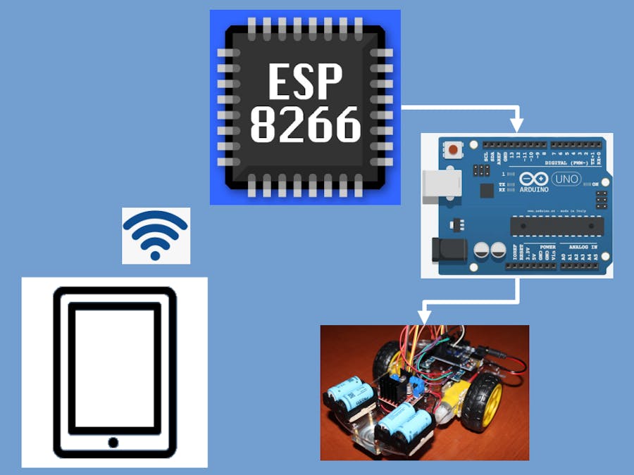
Block Diagram of control flowA high level block diagram below:
The ESP8266 is capable of been configured as a soft Access Point and initiates its own wireless network. The user device connects to this network and then can use the web page served up by the ESP8266 to send commands to the car via the ESP8266 and ATMega328.
The rest of this post will detail these steps.
First – the CarThis project uses a two wheel car. Kits for these cars are available from multiple sources. Here is a high level bill of materials:
- Two wheel drive kit including motors, chassis, various screws and nuts, wheels and wheel encoders.
- UNO R3 + WIFI ESP8266 + CH340G Arduino and WIFI single board
- L298N Motor driver bridge board
- 2 x HC-020K Encoder Module
- 4 x ICR16340 Lithium ion batteries and holders
- Toggle on/off switch
- Wireless Antenna
- Connection wires
This article does not include a description of how to build the car; there are many resources on the internet that explain the required steps.
Completed Car below:
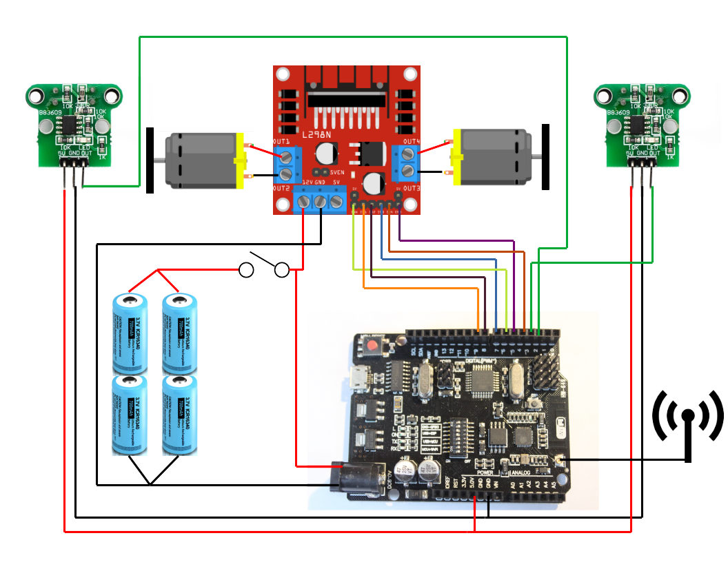
Circuit diagram of the completed car below:
Just a few points to note on the configuration:
- The car uses four ICR16340 700 mAh Lithium ion batteries in a parallel/series configuration. Two of these cells in series provide about 8 V when fully charged, which is enough to drive the motors and wifi/controller batteries in parallel is potentially problematic (you can get circulating currents), as an alternative the ICR16340 batteries come in a 2800 mAh version – two of these in series should be sufficient to power the car.
- Motor control is carried out by a L298N bridge driver module. Again, plenty of resources that explain how they operate and how to connect motors and controls.
- This circuit uses digital pins 5 and 6 for the PWM output to the L298N board to control motor speed. These are connected to ENa and ENb of the L298N board. Pins 4, 7, 8 and 9 are used to switch motors on and off.
- The circuit includes two HC-020K Encoder Modules. These are not specifically used in the code, but are available to provide speed or distance feedback.
- Depending on how your specific wiring is completed, motor leads may have to be swapped to get consistent direction. In addition, the HC-020K Encoder Module must be paired with the correct motor in the software (if used). This may be achieved by swapping interrupt 2 and 3 around or adjusting the software.
The ESP8266 can be configured as a wireless access point and web server. In addition, it can also be setup as a DNS server. This allows a client to access the web server with a local URL.
Before programming the ESP8266, you have to ensure that the Arduino IDE you are using is configured to do this type of programming. There are numerous articles on the Internet explaining how to do this. A search of “program ESP8266 from Arduino IDE” will provide many results.
Here are a few links:
https://www.instructables.com/Setting-Up-the-Arduino-IDE-to-Program-ESP8266/
https://randomnerdtutorials.com/how-to-install-esp8266-board-arduino-ide/
The basic steps are as follows:
- In File → Preferences, add a url to the Additional Boards Manager: http://arduino.esp8266.com/stable/package_esp8266com_index.json
- Under Tools → Boards → Boards Manager, Search for ESP8266 and install latest version of “ESP8266 by ESP8266 Community”
- Once this is done, you should have an option under Tools→ Board for a ESP8266 Boards. Choose Generic ESP8266 Module.
The relevant Arduino libraries used to set up Wifi, Web Server and DNS are:
ESP8266WiFi.h
ESP8266WebServer.h
ESP8266mDNS.h
These are installed as part of setting up the IDE to program an ESP8266 described above.
Here are the relevant code snippets to configure the ESP8266 as a soft access point.
#include <ESP8266WiFi.h>
const char *ssid = "ESP8266Network"; // The name of the Wi-Fi network that will be created
const char *password = "1234567890";   // Password for WiFi network. Must be more than 8 characters

void setup() {
  WiFi.softAP(ssid, password); // Start the access point
{
Above code will setup the ESP8266 as an access point and a client can connect to it, but nothing else will happen. First, let us configure the mDNS server to allow for easier URL access.
Code snippet below:
#include <ESP8266mDNS.h>

MDNS.begin("esp8266");

void loop() {
  MDNS.update();
}
Once a client is connected to the ESP8266 access point, a web browser can use the URL http://esp8266.local/ to access the ESP8266. Changing the argument “esp8266” in the begin() instruction will change the URL.
The relevant code snippet to set up a web server as follows:
#include <ESP8266WebServer.h>

ESP8266WebServer server(80);

void setup() {
  server.onNotFound(handlerRoutine);
  server.on(“URL”, handlerRoutine);
  server.begin();
}

void loop() {
  server.handleClient();
}
Where handlerRoutine is a subroutine that carries out various actions when a request is received from a client.
ESP8266 On Board file systemAnother feature of the ESP8266 is that it has an onboard filesystem, Serial Peripheral Interface Flash File System (SPIFFS), which can be used to store files. In our case, we can use this to store html files that are served to a connected client. The relevant library for this feature is:
FS.h
To enable this feature in the Arduino IDE, a plugin is needed: Filesystem uploader.
First, make sure you have the latest Arduino IDE installed, and you have the ESP8266 add-on for the Arduino IDE as described previously.
Then follow the instructions at either of these links:
https://randomnerdtutorials.com/install-esp8266-filesystem-uploader-arduino-ide/
https://github.com/esp8266/arduino-esp8266fs-plugin
Both links show how the filesystem uploader is used once the plugin is installed.
And now – HTML codeOnce the ESP8266 is setup as a web server, the relevant html page must be served to clients once they connect. This file is labeled index.html by convention. To understand this file, a knowledge of html code is required.
Some explanations:
- The file defines a single page and consists of four buttons (FWD, RIGHT, LEFT, BACK) and a speed slider.
- Depressing a button will cause it to change color and send a GET request to the ESP8266 web server
- The web server will process the GET request and use it to communicate with the ATMega328 to control the car
- Changing the speed slider will initate a POST request which will be used to set the speed value.
The full file (with comments) can be found in the code section of this post. Final page below:
As shown previously, the communication between the ESP8266 and the ATMega328 is via the serial port. To enable this communication, the on board DIP switches must be set as follows:
Set the dip switch to Mode 4 (SW1 and SW2 are On, all other are off)
The ESP8266 sends single characters between 1 and 8 to the ATMega328 to specify motor actions. The full code as follows:
// FWD Activate
    case '1':
    forwardOn();
    break;
// FWD Stop
    case '2':
    motorsOff();
    break;
// LEFT Activate
    case '3':
    leftOn();
    break;
// LEFT Stop
    case '4':
    motorsOff();
    break;
// RIGHT Activate
    case '5':
    rightOn();
    break;
//RIGHT Stop
    case '6':
    motorsOff();
    break;
// BACK Activate
    case '7':
    backOn();
    break;
// BACK Stop
    case '8':
    motorsOff();
The speed value is sent as a string with a “s” as the first character. The code then strips out the s from the string and does a string to integer conversion to set the motor speed.
Putting it all togetherHere are brief instructions for building the complete project:
- Build the Car
- Use Boards Manager in the Arduino IDE to select Generic ESP8266 module
- Upload the index.html file to the ESP8266 (DIP switches 5, 6, 7 on all others off) and then reset the processor
- Upload the ESP8266 program
- Remove power and set DIP switches to ATMega328 (DIP switches 3, 4 on all others off)
- Upload Arduino program (after selecting Arduino UNO in Boards manager)
- Remove power and set DIP switches to internal communication (DIP switches 1, 2 on all others off)
- Power up Car
- Connect tablet, smartphone or laptop to wireless to “ESP8266Network”
- From connected tablet, smartphone or laptop, open URL http://esp8266.local/
- Use interface to drive car
This project brings together a few diverse skills. Hopefully it is challenging.
It may be possible to achieve all of this functionality with a single ESP8266 board like the Node MCU, but this would be a separate project.


_3u05Tpwasz.png?auto=compress%2Cformat&w=40&h=40&fit=fillmax&bg=fff&dpr=2)


Comments
Please log in or sign up to comment.