This project shows how to use the Arduino with a X9C104 to implement a frequency generator such that the frequency is optimized using a feedback loop. This is the principle used in a PLL circuit.
This project shows how a X9C104 IC is controlled by an Arduino and used in a feedback loop with a 555 Timer circuit to output a user required input frequency. This frequency is set close to the input by using a feedback loop connected to an Arduino interrupt.
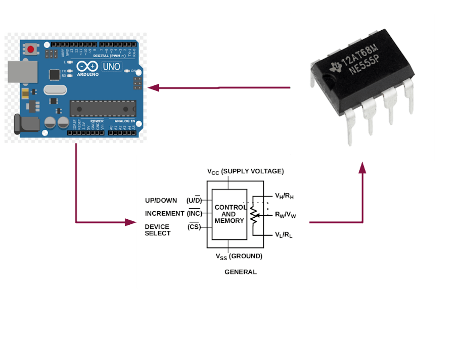
A simplified block diagram of the circuit shown below:
The basic principle of operation:
- User inputs a required frequency via the Arduino serial monitor.
- Arduino accepts input and programs X9C104 to an initial setting
- X9C104 resistance in 555 timer circuit adjusts frequency of oscillation
- The resulting square wave is fed back into the Arduino interrupt (pin 2)
- Using an interrupt handling routine, the frequency of the square wave is determined
- This frequency is compared with the required and adjustments are made to X9C104
- Frequency is measured again and a second optimization is performed
- Frequency of output square wave from 555 timer settles to value set by user in step 1
X9CXXX Digitally Controlled Potentiometer (XDCP)
The X9CXXX integrated circuits are manufactured by Intersil (recently acquired by Renesas Corporation) and represent their range of digitally controlled potentiometers. The device includes a resistor array, control section and non-volatile memory. The resistance of the array is controlled by a three wire digital interface.
A block diagram from the Intersil data sheet:
The device can be used as two terminal variable resistor or a three terminal potentiomenter. It includes non-volatile memory that holds the last resistance value on power down and sets the resistor array to this value on subsequent power up.
Control of the wiper position and hence the resistance is determined by the three digital inputs:
- Device is selected by taking CS low.
- State of Up/Down (U/D )determines whether the wiper moves closer to Vh/Rh or Vl/Rl.
- The wiper moves one step every time INC is taken low and then returned to high.
- The wiper has 100 possible positions (0 – 99), allowing for incremental steps of 1% of the total resistance.
- When the wiper reaches the top or bottom ( Vh/Rh or Vl/Rl), it does not move any further nor does it wrap around to the other extreme.
It is important to remember that the wiper moves a single increment for each INC cycle. The wiper cannot jump across multiple steps. This means that moving from step 10 to step 20 requires 10 INCcycles.
Vh and Vl cannot exceed Vcc and Vss.
Complete specifications for the devices can be found at the Renesas website.
https://www.renesas.com/us/en/document/dst/x9c102-x9c103-x9c104-x9c503-datasheet?r=502676
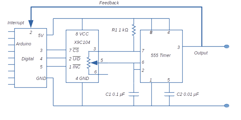
Project CircuitThe 555 Timer circuit used in this project is a standard astable oscillator. There are multiple articles available that document the workings of this circuit and a quick search will access to the explanations.
At a high level, operation as follows:
- With pin 7 high, capacitor C1 charges up through R1 and the variable resistor in the X9C104
- At a certain threshold voltage, the 555 timer internal flip/flop s1witches and Pin 7 goes low
- Capacitor C1 then discharges through the variable resistor in the X9C104.
- At the lower threshold voltage, the 55 timer internal flip/flop switches back and the cycle repeats.
The equations for frequency and duty cycle as follows:
In the circuit used here, R2 is 100 kΩ(X9C104) and R1 is 1 kΩ. Because of the difference, the frequency and duty cycle of the circuit is effectively set by the value of R2, except at very low values of R2. This means that R1 can be ignored and the frequency equation can be simplified to:
To calculate a resistance change that will result in a desired frequency change, some math will show
Values of R1, R2 and C1 are chosen so that the circuit will generate square waves within the audible frequency range.
The photograph at the beginning of this article shows the physical circuit.
Arduino InterruptsThe ATmega328P at the heart of the Arduino board accepts interrupts. An valid interrupt halts current program flow and starts a interrupt service routine which completes some actions before handing control back to the previous program flow.
For a detailed description of Arduino interrupts consult the Arduino language reference and the fine article written by Nick Gammon
Be aware that some of the standard functions available in the Arduino instruction set such as delay() and millis() will not work in an interrupt service routine as these functions rely on interrupts themselves to work.
In the Arduino code, an interrupt is turned on using the attachInterrupt() command. The specific version of the command used in this project is as follows:
attachInterrupt( digitalPinToInterrupt(interruptPin), trig_detected, RISING );
interruptPin specifies the digital pin on the Arduino that accepts the interrupt, trig_detected is the Interrupt Service Routine (ISR) that processes the interrupt and RISING is the state change that triggers the interrupt.
Once an interrupt has completed its function, they can be turned off by using:
detachInterrupt(digitalPinToInterrupt(pin))
In this project, as we are using a square wave to trigger the interrupt, each transition from low (0V) to high (5V) (a rising waveform) will cause trig_detected to start.
Arduino Code for this projecthe code makes use of the Fast X9CXXX library for the Arduino. The library is available on GitHub at:
https://github.com/GitMoDu/FastX9CXXX
Make sure that the code is downloaded and included in your Arduino library folder before compiling the code.
The overall flow of the function is described in the introduction.
The setup part of the program initiates the X9C104 object using pins 3, 4 and 5 from the Arduino. Potentiomenter is set to 50 step (midway).
The main loop waits for an input from the user via the Serial monitor; this input must be a desired frequency. Because of the design of this project, input frequency can be between 80 Hz and 550 Hz and is entered as a single number (example 80 or 550). If the values of C, R1 and R2 are changed, different frequencies will be generated.
Some additional notes:
- The interrupt service routine (ISR) in the code is called void trig_detected (). It returns two values derived from micros() which is then subtracted from each other to get a duration between interrupt events. This duration is the inverse of square wave frequency.
- 12 samples of the square wave duration are taken and stored in an array (trigArray). The average of the last 10 is computed.
- These frequencies are used to calculate a ΔR value which is used to set a potentiomenter value.
- Two tuning routines are carried out to make frequency equal to the input value.
Frequency measurements of the circuit were taken at various input values. The results are tabulated in the attached below:
Of course, there are inherent limitations to this circuit. The major limitation is the step nature of the potentiometer. Because of the frequency to resistance equation, single potentiometer steps cause wide frequency jumps at higher frequencies.
Also, the use of micros() in the ISR may not work at different frequencies. Use of timer registers can get around this problem.
But a interesting project with multiple applications.


_ztBMuBhMHo.jpg?auto=compress%2Cformat&w=48&h=48&fit=fill&bg=ffffff)


Comments
Please log in or sign up to comment.