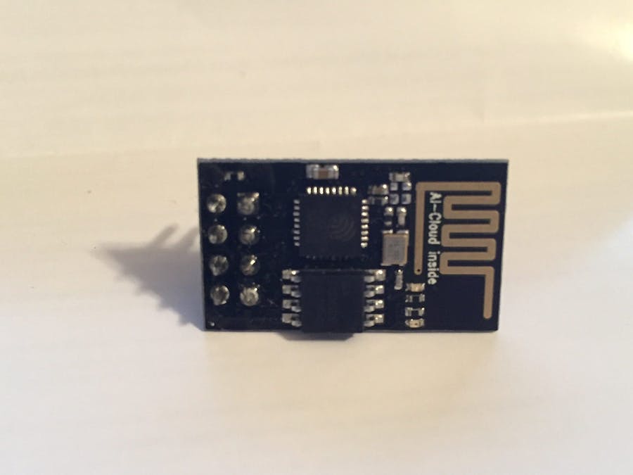
This is a tutorial from BreakoutBros.com. See the full tutorial here. A couple weeks ago we looked at an Internet of Things solution, the Particle Photon. After getting a lot of feedback from the community we got our hands on Riaspire ESP8266 WiFi board. This one of the many ESP8266 boards out there.
The ESP8266, like the Photon, is a a WiFi enabled microcontroller module that can be used as a solution to any IoT project. However, as the Particle Photon was very simple to get setup and running with all of its support, the ESP8266 is leaps and bounds harder making the ESP8266 definitely not for beginners. The documentation is hard to find and a lot of Google searches return examples that either skip steps or are just wrong. For this tutorial I hope to bring this information to one place to get you up and running faster using an Arduino to setup and make sure the ESP8266 is working.
With the ESP8266 being much more difficult to get started with, why even use the ESP8266? Well there are two really big benefits to the ESP8266 which depending on the project could outweigh almost any other IoT device like the Photon.
PriceThe price of the ESP8266 is just unbeatable on the magnitude of 1/4 the cost of some of the other solutions. If you are on a tight budget or need to make a lot of something, learning the ESP8266 will be well worth your time.
CustomizationThe ESP8266 is completely open unlike the Particle Photon. You aren’t trapped into using someone else’s cloud, or IDE, like Particle, and you don’t need the “support” enabled in order to use it. you have more freedom with how you use the ESP8266 to fit the needs of whatever your project is. You can make your ESP8266 a personal server or put it in AP mode to act as a WiFi access point. The ESP8266 will also teach you a lot more than the Photon as a lot of what the Photon is doing in the background with it’s integration with Particle, you get to learn how to do this yourself.
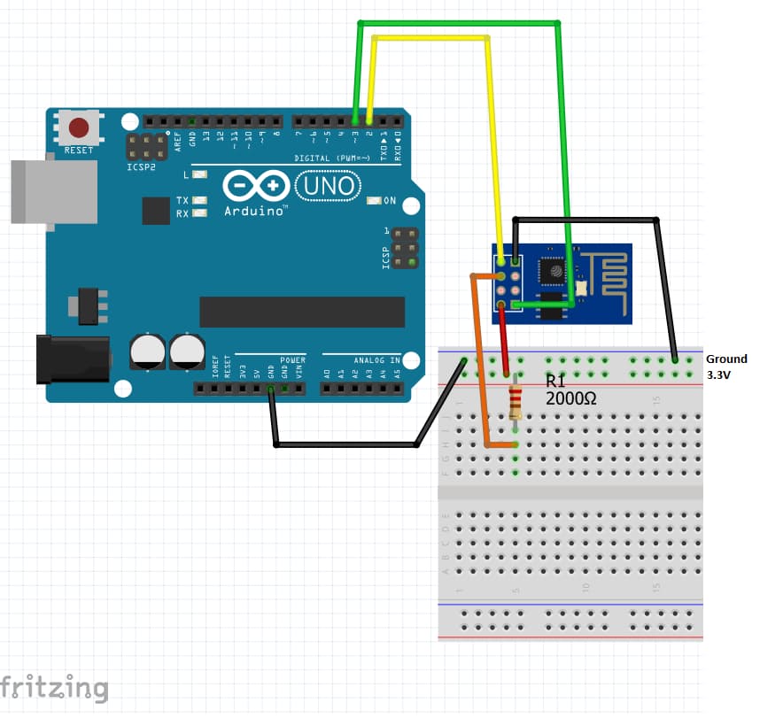
Setting Up the HardwareLike the Photon, the ESP8266 is a 3.3V device so you must use 3.3V to power it. DO NOT use the Arduino 5V as this will damage the ESP8266 permanently. The 3.3V supply in the standard Arduino also doesn’t supply enough current to power the ESP8266 during its peak transients. Use a 3.3V power supply with at least 500 mA of current. I used the 3.3V supply in the Elegoo 37 Sensor kit. It was perfect because it fits in a standard Breadboard, making one side rail 3.3V and the other side rail 5.0V.
You can use the ESP8266 in a couple ways. In this tutorial we will only demonstrate that it is functioning by Serial mirroring the Arduino IDE Serial port to a Software Serial port connected to the ESP8266. This will also allow us to change some of it’s setting and get it connected to your Home WiFi. You could also buy a Serial USB to TTL converter and use a command based serial program like Putty to send these commands. I did not have a Serial USB to TTL converter so I opted to just use an Arduino and Serial mirror the commands. If you use a Serial USB to TTL converter please be sure to also use a level shifter so that you don’t apply 5V to the ESP8266.
There is also a ESP8266wifi library and Arduino IDE addition you can add that includes libraries for using the ESP8266 which you can use to directly program instead of just sending commands with a prompt. Ultimately this will be the easiest way to setup the ESP8266 for most IoT projects but this deserves a whole separate article.
SchematicConnect the ESP8266 TX pin to pin 2 of the Arduino, RX pin to pin 3 of the Arduino and make sure the 3.3V supply’s GND and the Arduino GND are connected. Next pull up the ESP8266 Enable pin to 3.3V using a high 2k resistor. You will be powering the Arduino through its USB port, this will also be how you communicate to the ESP8266.
Code for the ArduinoI found the Idea to serial mirror the ports from this source. Go ahead and go to this site to grab the code. It basically just looks for whenever serial is available and it prints it to the software ESPSerial and whenever software ESPSerial is available it prints it to serial. You will need to first change the baud rates for the Serial.begin and ESPSerial.begin form (9600) to (115200). Go ahead and upload this to the Arduino you are using. Once installed open the Serial Monitor. As noted in the code, make sure both NL & CL are selected for viewing on the bottom and 112500 is set as the baud rate.
Now that the Serial Monitor is up and running, you can power on the ESP8266 and you should see some boot commands, however it will be VERY jumbled. This is because the ESP8266 is set to a 115200 Baud Rate and the Software Serial of the Arduino simple can’t keep up at that speed.
Type “AT” in the serial text box and if you see “OK” as a response then you are correctly connected. Again this might still be a little jumbled with some gibberish mixed in. You can see this jumbling below in the “re’dy” and the Box next to the AT.
Change the ESP8266 Baud rate by typing
AT+UART_DEF=9600,8,1,0,0
You should receive an OK.
Now whenever you type you should not see a response. First exit the program and change the Serial.begin(115200) and the ESPSerial.begin(115200) to Serial.begin(9600) and the ESPSerial.begin(9600). Now open the Serial monitor again and make sure you select 9600 as the Baud Rate. Now type in the AT command and you should get OK again.
If you are not getting any response here are some things to try:
- Verify that you are using a 3.3V power supply for the ESP8266 that is at least 500mA
- Verify the GND of the ESP8266 and the GND of the Arduino are connected
- Verify that the TX pin of the ESP8266 is going to pin 2 of the Arduino and the RX pin of the ESP8266 is going to pin 3.
- Verify the EN pin of the ESP8266 is pulled up to 3.3V with a 10k resistor
- If you haven’t changed the Baud Rate of the ESP8266 make sure 115200 is written in the Arduino Program for the
serial.begin()and that 115200 is selected as the baud rate for the Arduino Serial Monitor
- If you have changed the Baud rate of the ESP8266 to 9600 make sure 9600 is written in the Arduino Program for the serial.begin() and that 9600 is selected as the baud rate for the Arduino Serial Monitor
- Make sure Both NL& CL is selected
- If you continue to have issues you may have an ESP8266 with a different starting baud rate than 115200, an incorrect wiring, or a damaged ESP8266.
You can check out all the commands for the ESP8266 here: We will only be using some of them for this tutorial. First make sure the Mode of the ESP8266 is mode 1 by using
AT+CWMODE=1
If this worked you should have recieved an OK. Next see what networks are available by using:
AT+CWLAP
Next select your network and type in:
AT+ CWJAP=”YOUR_SSID”,”YOUR_PASSWORD”
*Please note that “YOUR_SSID” is the SSID for your WiFi network and “YOUR_PASSWORD” is the password for you WiFi network. You should see a “WiFI Connected” then a “WiFi Got IP” followed by OK if the connection is successful.
To get the IP Address of your ESP8266 you type in:
AT+CIFSR
This will be your Local IP address. Now if you want to see something cool open up the CMD prompt and PING this IP address:
It has 4 successful pings! Now you have successfully connected your ESP8266 to your Home WiFi and are pinging your ESP8266 with your computer over WiFi. Stay tuned and subscribe so you don’t miss any reviews or tutorials! We plan to continue to use the ESP8266 for more projects.


_ztBMuBhMHo.jpg?auto=compress%2Cformat&w=48&h=48&fit=fill&bg=ffffff)


Comments
Please log in or sign up to comment.