

Hardware components | ||||||
_ztBMuBhMHo.jpg?auto=compress%2Cformat&w=48&h=48&fit=fill&bg=ffffff) |
| × | 1 | |||
 |
| × | 1 | |||
 |
| × | 1 | |||
 |
| × | 1 | |||
| × | 1 | ||||
 |
| × | 3 | |||
 |
| × | 3 | |||
This is a BreakoutBros.com tutorial. See the full version here.
After reviewing the Particle Photon, I wanted to go back to one of our tutorials and add some IoT (Internet of Things) functionality using the Photon. In this tutorial I’ll walk through how to have the Particle Photon email you by adding this capability to our RFID Badge Scanner with LCD tutorial.
If you have not seen the RFID Badge Scanner with LCD tutorial, the first thing you will need to do is visit this article and get setup so that you can scan a RFID badge and display a “welcome home” message to a user you associate with the RFID tag.
What you will needIn addition to the materials needed for the RFID badge scanner you will need:
- 3x 10K resistors*
- 3x 2k resistors*
- Wires and Breadboard*
*note you can get these off amazon or any electronics store or you can check out one of the Arduino Starter Kits that will include these basic components.
5V to 3.3V level shiftingFor this tutorial we will be using the Arduino to communicate directly to the Particle Photon using three different I/O pins. If the first pin is High it will indicate that the 1st user’s badge was scanned, if the 2nd pin is High it will indicate that the 2nd user’s badge was scanned and if the 3rd pin is High it will indicate that the 3rd user’s badge was scanned.
The Particle Photon uses 3.3V logic while the standard Arduino uses 5v logic. In order to “safely” have them communicate using I/O pins, we will need to develop a level shifter that shifts 5V to 3.3V. Although it will work to directly connect 5V to the Particle Photon I/O it is not good practice. This stresses the pins and can potentially damage the I/O. This is even more important if we were using the Analog pins as this puts extreme stress on the analog to digital converter. Particle explicitly states not to directly connect 5V to those pins.
The 5V to 3.3V level shifter circuit is a simple NPN transistor and some biasing resistors.
This circuit will take a 5V output on the Arduino Pin and shift it to a 3.3V input on the Photon pin. If the Arduino Output is 0, the Photon input pin will also be 0.
You will need three of these circuits, one for each of the pins that will go between the Arduino and Photon. Follow the pinouts below.
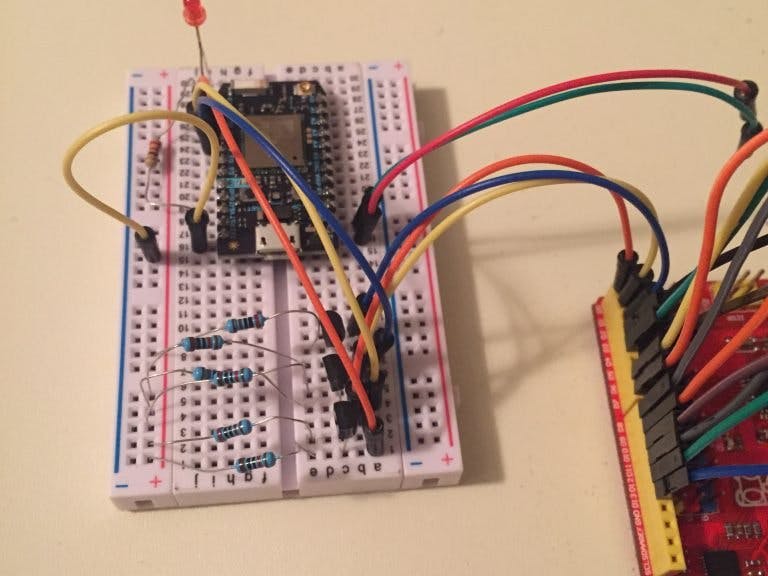
Next wire these three circuits using a breadboard. The Particle Photon starter kit comes with one along with the Arduino Starter Kits.
Power the Photon using the Arduino 5V output by connecting VIN on the Photon to 5V from the Arduino. This will go through the Photon’s voltage regulator to drop the voltage to it’s needed 3.3V. Also do not forget to connect GND from the Photon to GND on the Arduino.
Now your Arduino and Particle Photon are setup to communicate using a 5V to 3.3V level shifter. It’s time to begin coding the Particle Photon.
As discussed in the Particle Photon Review an online IDE is used to program. Go to www.Particle.io/build and login to your particle account. Create a new program. We will be setting this program up to publish an event based on certain inputs the Photon will read from the Arduino. This event will later be used as a trigger to email you. The code will also include some functionality for the LED to visually tell when and to who it is sending an email. The LED will blink at a different rate depending on to whom it is sending an email.
Particle Photon CodeFirst define all the global variables
int led1 = D0; //LED to show changes in states
int led2 = D7; //LED to show changes in states

int firstBitPin = 1; //Pin that will be reading the first Bit to know state
int secondBitPin = 2;//Pin that will be reading the second Bit to know state
int thirdBitPin = 3; //Pin that will be reading the third Bit to know state

int firstbitState = LOW; //variable to store the state of the first Bit
int secondbitState = LOW;//variable to store the state of the second Bit
int thirdbitState = LOW; //variable to store the state of the third Bit


int LEDDelay = 1000; //Variable used to change the LED blink timer based on what Bits are high
This includes all the Pins that will be used and the data bits that will be stored based on what the Arduino outputs. Also define the LED Blink rate at 1 second.
Next we will go through the setup loop mainly to define all pin outputs and variables to initialize as
void setup() {


  pinMode(led1, OUTPUT);  //Set the LED pin to an Output
  pinMode(led2, OUTPUT); //Set the LED pin to an Output

  pinMode(firstBitPin,  INPUT);//Set the BIT 1 pin to an input(used for transfering who is scanned)
  pinMode(secondBitPin, INPUT);//Set the BIT 2 pin to an input(used for transfering who is scanned)
  pinMode(thirdBitPin,  INPUT);//Set the BIT 3 pin to an input(used for transfering who is scanned)

  digitalWrite(firstBitPin,  HIGH); //enable pullup
  digitalWrite(secondBitPin, HIGH); //enable pullup
  digitalWrite(thirdBitPin, HIGH);  //enable pullup

  digitalWrite(led1, LOW); //Make sure LED 1 starts in LOW state

}
The last part of code will be the main loop. This will tell the photon to react based on what Bits it reads from the Arduino.
void loop() {
  firstbitState = digitalRead(firstBitPin);  //Read bit 1 and store
  secondbitState = digitalRead(secondBitPin);//Read bit 2 and store
  thirdbitState = digitalRead(thirdBitPin);  //Read bit 3 and store

  if(firstbitState == HIGH) // This will only work for 3 of the combos;(0,0,1)(0,1,0)or (1,0,0)
  {
      Particle.publish("RFID_HOME","JOSH"); // Particle Command to publish the Event "RFID_HOME" with the data JOSH
      LEDDelay = 250;                       // this means Josh's badge was scanned. we also change the LED blinking to 250
      delay(5000);                          // 5 second delay after publshing, this will prevent 2 publishes from one eveent from the arduino.
  }
  else if(secondbitState == HIGH)
  {
      Particle.publish("RFID_HOME","BRAD");  // Particle Command to publish the Event "RFID_HOME" with the data BRAD
      LEDDelay = 500;                        // this means Brads's badge was scanned. we also change the LED blinking to 500
      delay(5000);                           // 5 second delay after publshing, this will prevent 2 publishes from one eveent from the arduino.
  }
  else if(thirdbitState == HIGH)
  {
      Particle.publish("RFID_HOME","SAM");   // Particle Command to publish the Event "RFID_HOME" with the data SAM
      LEDDelay = 1000;                       // this means Josh's badge was scanned. we also change the LED blinking to 1000
      delay(5000);                           // 5 second delay after publishing, this will prevent 2 publishes from one event from the arduino.
  }
  else
  {
      LEDDelay = 2000;                      //If none of the bits are set, we store 2 seconds for the blinking, this is"normal" blink time

  }
    digitalWrite(led1, HIGH);               //Set LEDs high as a heartbeat
    digitalWrite(led2, HIGH);
    delay(LEDDelay);                        //Use the delay stored above
    digitalWrite(led1, LOW);
    digitalWrite(led2, LOW);                //Set LEDs LOW as a heartbeat
    delay(LEDDelay);                        //Use the delay stored above
}
The main loop will first read the state of the pins and store these into its appropriate variable. Then depending on which bit is high it will execute the Particle.publish(“EVENT”, “DATA”) command. The first data input to the Particle.publish command is the “event” and the second input is the “DATA”. We will call this the “RFID_HOME” event and the Data is the user badge name . Also, for each user a different LED blink time is used. This way you can visually detect if the Photon sensed a particular badge based on the data. The Delay after executing the Particle.publish command is to ensure that the Photon doesn’t send multiple events for a single scan from the Arduino. The last bit of the code loop is to blink the LED at the LEDDelay rate. You can get the Photon Particle code for this tutorial here.
Setting up IFTTT For the IoT EmailNow that the particle is publishing the RFID_HOME event to the particle cloud, you now need to setup a service that will look for this data being published. For this tutorial we will be using If This Then That. Go ahead and go to ifttt.com and create an account.
Search for particle then click on the Particle Icon under services:
Next you will need to select an Applet that uses Email. Scroll down and select “Test of Electron Beam Switch”
Flip the switch to turn this applet on
Once the Applet is on it will allow you to edit.
This is setting up the service to email. Label the name of this Applet based on the Badge Name you want emailed. You then need to put the Event the Particle published in the “If(Event Name)” box. This was “RFID_HOME”. Then put the contents for this publish event into the “is(Event Contents)”. For this applet it will be JOSH – it MUST match what’s in the Particle Photon Code. Now press save and then go back into edit.
For some reason you must save then go back into the Applet to get the Email portion setup. This is how you format your email. The subject will be “{EventContents} has entered the front door” and the Body will be “Hey, your {DeviceName} has logged that {EventContents} has entered the front door. Welcome them Home.”
All that is left for the IoT is to setup two more applets for the other badge names – SAM and BRAD
Once all of this is setup, you should test that everything is working with the Particle Photon. Do this by manually pulling each pin (1 through 3) high one at a time on the particle Photon for a couple seconds to confirm that the LED starts blinking at a different rate. Then check the email you have setup for ifttt.com to make sure you receive the email. Pulling Pin 1 HIGH should send the “JOSH” email, pulling pin 2 HIGH should send the “BRAD” email and pulling pin 3 HIGH should send the “SAM” email. Please note that the other pins MUST be low when doing this otherwise you will get the email for the first name in the IF statements. Once this is working you are ready to connect the RFID Badge Scanner with LCD system.
Arduino Code sent to Particle PhotonSince the RFID Badge Scanner is already pulling the RFID badge and attaching a Name to each badge ID, all you will need to do is setup which pins need to go HIGH and LOW for each Name and then add in code that will set these pins appropriately whenever that Badge ID is read.
First define these new pins and arrays for Pin Data:
///Email Variable
int outFirstBitPin = 0; //Pin that will be connected to Photon for bit one data
int outSecondBitPin = 1;//Pin that will be connected to Photon for bit two data
int outThirdBitPin = 2; //Pin that will be connected to Photon for bit three data

int RFID_JOSH[]   = {1,0,0}; //Parallel Data for JOSH tag to send to Photon
int RFID_BRAD[]   = {0,1,0}; //Parallel Data for BRAD tag to send to Photon
int RFID_SAM[]    = {0,0,1}; //Parallel Data for SAM  tag to send to  Photon
Next add in code that will set these pins based on the name read:
 if(Tag_Name != "i")
            {
                  lcdprintwelcome(Tag_Name);

                  if(Tag_Name == "Brad") //If the name is BRAD we send the parallel data to the Photon to send the email that Brad Scanned
                  {
                    digitalWrite(outFirstBitPin,  RFID_BRAD[0]);   //Send first bit data for Brad
                    digitalWrite(outSecondBitPin, RFID_BRAD[1]);   //Send second bit data for Brad
                    digitalWrite(outThirdBitPin,  RFID_BRAD[2]);   //Send third bit data for Brad

                    delay(5000); //Wait 5 seconds after sending the data to ensure the Photon reads it during its loop

                    digitalWrite(outFirstBitPin,  0);   //set data back to 0
                    digitalWrite(outSecondBitPin, 0);   //set data back to 0
                    digitalWrite(outThirdBitPin,  0);   //set data back to 0
                  }
                  else if(Tag_Name == "Josh") //If the name is BRAD we send the parallel data to the Photon to send the email that JOSH Scanned
                  {
                    digitalWrite(outFirstBitPin,  RFID_JOSH[0]);   //Send first bit data for Josh
                    digitalWrite(outSecondBitPin, RFID_JOSH[1]);   //Send second bit data for Josh
                    digitalWrite(outThirdBitPin,  RFID_JOSH[2]);   //Send third bit data for Josh

                    delay(5000); //Wait 5 seconds after sending the data to ensure the Photon reads it during its loop

                    digitalWrite(outFirstBitPin,  0);   //set data back to 0
                    digitalWrite(outSecondBitPin, 0);   //set data back to 0
                    digitalWrite(outThirdBitPin,  0);   //set data back to 0
                  }
                  else if(Tag_Name == "SAM") //If the name is BRAD we send the parallel data to the Photon to send the email that SAM Scanned
                  {
                    digitalWrite(outFirstBitPin,  RFID_SAM[0]);   //Send first bit data for Sam
                    digitalWrite(outSecondBitPin, RFID_SAM[1]);   //Send second bit data for Sam
                    digitalWrite(outThirdBitPin,  RFID_SAM[2]);   //Send third bit data for Sam

                    delay(5000); //Wait 5 seconds after sending the data to ensure the Photon reads it during its loop

                    digitalWrite(outFirstBitPin,  0);   //set data back to 0
                    digitalWrite(outSecondBitPin, 0);   //set data back to 0
                    digitalWrite(outThirdBitPin,  0);   //set data back to 0
                  }
                  lcdprintmain(); //Go back to Main scan screen
            }
            else
            {
                lcdaccessdenied();//If the read tag isnt in our data base, we will print an Access Denied message
                delay(2000);
                lcdprintmain(); // refresh to home screen
            }
Once the Success criteria for detecting a valid tag is met, if the name associated to the tag is equal to “Josh” “Brad” or “Sam” the appropriate pin output will be sent to the Particle Photon. A delay of 5 seconds is added after the pins are set so that the Particle Photon has time to detect the pin change. After the delay, the pins are set back to 0 so that no more “emails” will be sent. Get the full Ardunio code here.
Now you have successfully added the Particle Photon to make the RFID Badge Scanner with LCD an IoT device. Whenever one of the defined badges is scanned an email is sent to you. Now add this to your front door and control a lock solenoid and you have a monitoring system for your house front door lock. You can be emailed when someone badges in so you know if someone is home regardless of you being present or not!
I hope you enjoyed and learned from this tutorial. Please be sure to subscribe so you do not miss future articles. We plan on adding some more functions to the RFID Badge Scanner so stay tuned!


Comments
Please log in or sign up to comment.