The computational power of the RT1010 crossover processor presents an opportunity to use two very inexpensive OV7670 camera modules to create a low cost stereoscopic rangefinder.
Advantages over other techniques
- A view can be developed like a radar display classifying objects by size and distance to the drone that is very detailed compared to other sensor methods. The limitations are in the computational power of the system and not the limitations of the sensor.
- The cameras can be directed in multiple axes to cover all directions around the drone.
- Much more practical than an ultrasonic rangefinder, since fewer sensors are required to cover multiple directions and propeller sound is not messing up sensor input, as it does an ultrasonic rangefinder. A camera would still probably needed to further qualify an object detected with ultrasonic methods.
- Laser time of flight sensors have a very narrow detection angle, so a scanning method or multiple sensors must be used to cover multiple directions. A camera is still probably needed to further qualify an object detected with a laser time of flight methods.
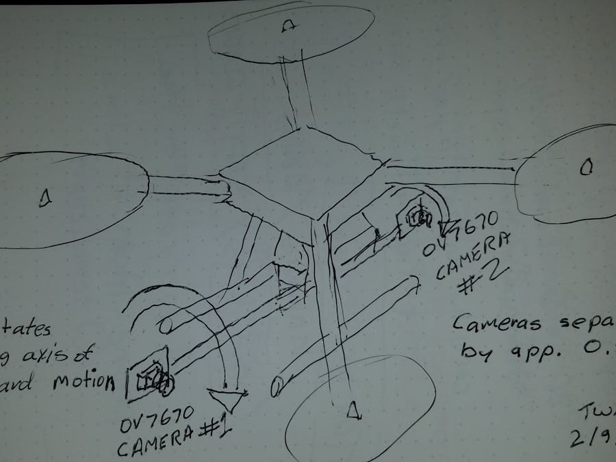
The stereoscopic cameras are mounted separated by approximately 0.5 meter. The axis of rotation is along the drone direction of forward motion. The cameras can be rotated to look from one side, down, to the other side , and up.
With a slightly more elegant drone frame, that uses retractable landing gear, a second axis of rotation for the stereoscopic rangefinder can be added.
The more elegant drone frame is not strictly needed, since the drone can easily rotate in flight to provide the additional second axis of motion.
The stereoscope electronics will use Bluetooth serial modules to communicate with the drone FMU and have a separate battery, no wires will complicate and limit range of motion. 360 degree servos with no stops are used to direct the OV7670 cameras.
A pulley and gear system will be used to rotate the cameras and RT1010 processor. I would like to mount the cameras to a square sectioned carbon fiber boom but for cost reasons may have to use a lower cost material. The square section is preferred to keep the cameras in alignment with each other.
About stereoscopic rangefinders
Software Development
- Download the FlexIO Parallel camera demo code another link
- Download and install an evaluation copy of IAR development environment
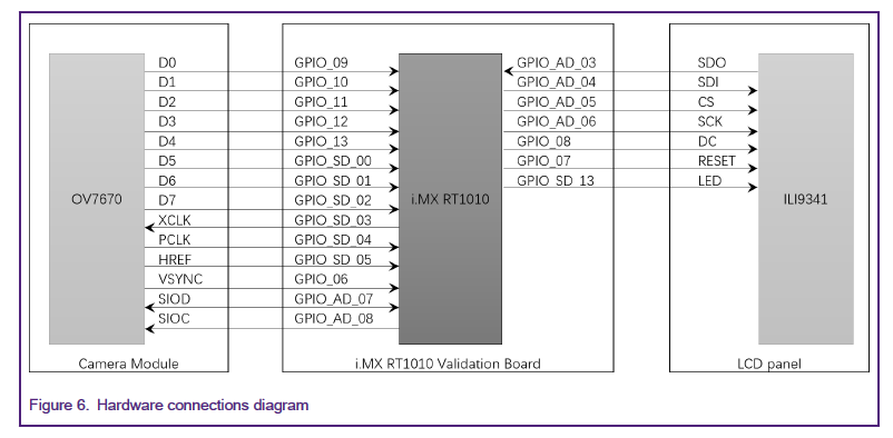
- Get familiar with the FlexIO Parallel camera application note . Please note the following text from the application note
There is some work to be done attach wires to gain access to the FlexIO pins and move some of the pin assignments to the Arduino connectors to ease the construction of the project. I have included a spreadsheet to keep track of possible connection places for various functions in the application note, I will not use a LCD display in the final package of electronics for a drone, but I do want to use the display in the software development process. Also remember I want to use two camera modules to act as a stereoscopic range finder, so I must put together some electronics to act as a switch between two cameras.
After studying the schematic for the RT1010 EVK and what is involved to solder to the boards the wires needed for the FlexIO connections, I have decided that soldering to such small connections would be foolish to attempt. I really don't want to ruin the RT1010 EVK.
The backup plan
The FRDM-K82F board has easily accessible FlexIO connections. Until I have a RT1010 based board with easy FlexIO connections, the FRDM-K82F will be used to prove the camera switching techniques. There is quite a bit of software to be written for evaluating stereoscopic scenes and presenting it in a useful format for drone use. For a good portion of the RT1010 firmware development, we really don't care how the picture data arrives in the RAM of the RT1010 processor.
A purpose built board for the RT1010 will likely permit two FlexIO camera interfaces to be constructed such that pictures from both cameras can be simultaneously brought into RT1010 RAM. Simultaneous sampling of the cameras would be ideal.
Hardware For supporting 2 cameras
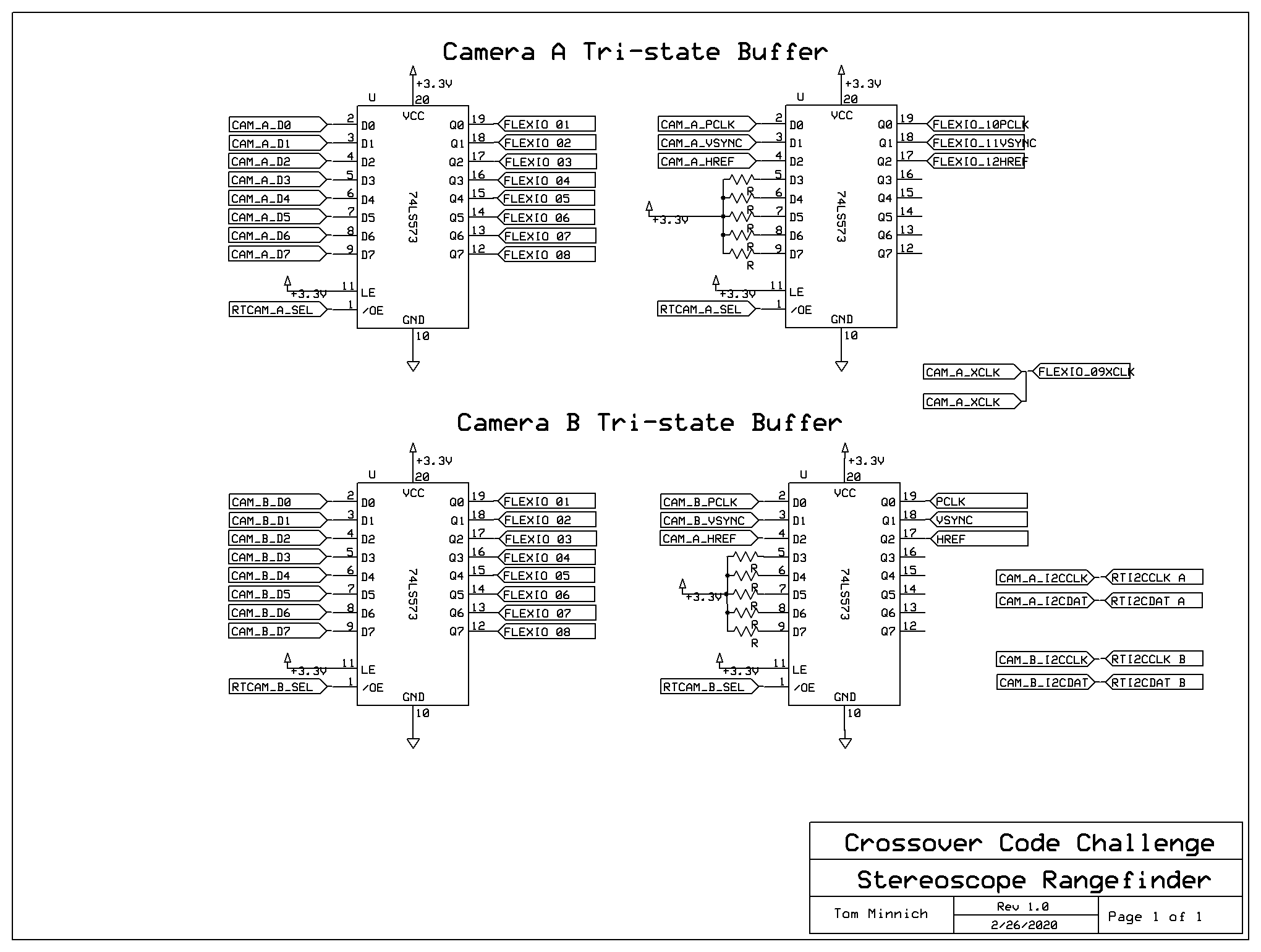
74HC573 octal latches with tri-state buffers will be used to keep the cameras from interfering with each other. 8 data lines are buffered with one 74HC573. The PCLK, HREF and VSYNC signals must also be buffered through another 74HC573.
A line is dedicated to tri-stating the lines of one camera while the other camera is being used.


Comments
Please log in or sign up to comment.