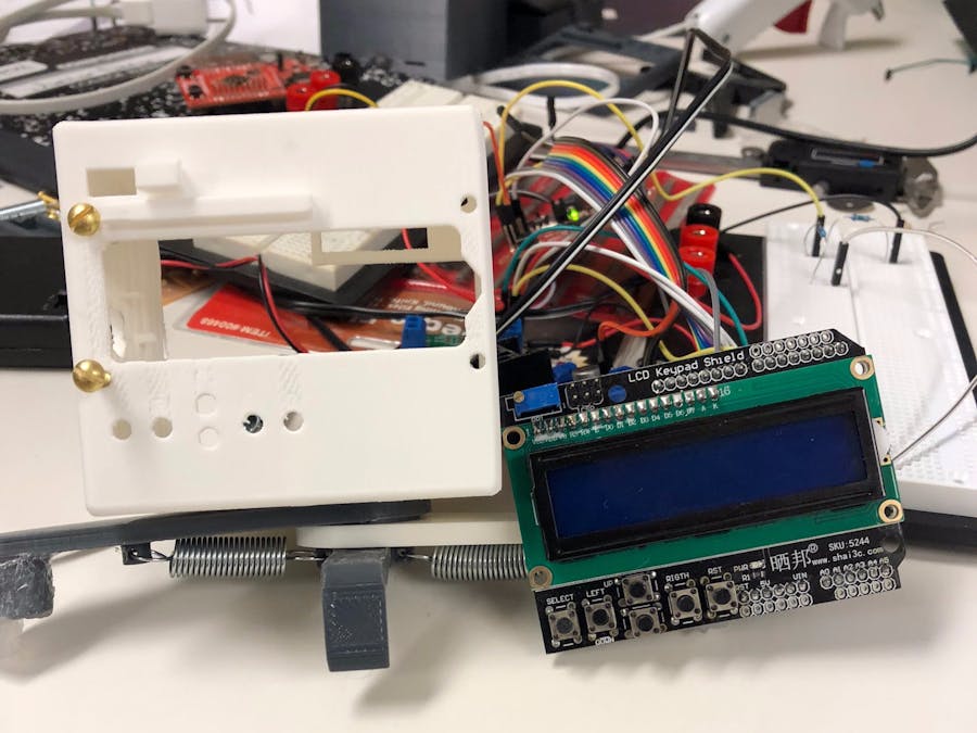
The purpose of this project was to demonstrate our mastery of the concepts learned throughout an embedded systems course. This project utilizes several areas covered in embedded systems, and proved a difficult challenge for our team. The goal of this project was to create a device which allows the user to select a certain frequency to tune a guitar string to, and then tune it automatically. The user would pluck the string, and as the guitar listens to the frequency created, the device would turn the tuning stud to raise of lower the frequency. This project makes use of analog to digital input from a microphone, frequency detection, state machine control, LCD user interface, and motor control. We implemented this project with the TI Tiva C Board due to its wide range of capabilities. This project made use of the TivaWare driverlib library to allow the easiest use of the board. For other functionalities, heavy use was made of the previous projects in this course, including the project with the character LCD. The functions used may be viewed in the included code.
The project was created by working from two ends and bringing the project together at the end. These two parts being the frequency detection and the LCD.
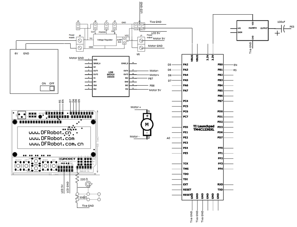
To supply power, a 6V battery pack was used, along with a voltage veduction module which sends out 5V to multiple outputs. The Tiva C board has a Vin bus port made for 5V. The motor was controlled using an H-Bridge module with a separate power supply for the motor, so that the board does not need to supply current to the motor. The module also allows the board to drive the motor forwards and backwards. For the User Interface an Arduino LCD Shield was used and connected to the Tiva board. After analysis of the shield, the LCD and buttons were able to be operated by the Tiva board without issue. In order to protect the 3.3V pins of the Tiva, the 5V voltage from the LCD buttons was stepped down with a simple voltage divider. The motor used was a 6V DC Gear Motor, with a ratio of 1:1000. The microphone used was an Adafruit Electret Microphone sensor with automatic gain control. This automatic gain control allows the microphone to adjust based on how loud the sound of the guitar is, and allows the tuner to still get a good reading of the input sound. This microphone was read with an ADC pin, from which the information was sent to the frequency detection algorithm. All of these components were made to fit inside of a 3D printed case.
The LCD was controlled using a state machine. This machine looks for button inputs from the shield, and navigates the interface accordingly. The shield calls different displays to output to the board, and waits for the next user input. When the user selects to begin tuning, the device enters tuning mode. In tuning mode the device calls the tuning algorithm repeatedly, and checks whether to change direction of the motor repeatedly. The program stays in this mode until the user selects to quit. This algorithm allows the device to narrow in on the correct frequency. In this mode, every return of the algorithm function also updates the display as to what frequency the device hears. This allows the user to see how far away the device is from being tuned. To account for extraneous noise in signal sent from the microphone to the Tiva board, the signal was sent across a 100µC Capacitor. However, even with the aid of a capacitor the signal picked up by the microphone was heavily influenced by both noise generated from the wires, outside noise, and the harmonics of the various strings. There were several options readily available for analyzing the frequency of the incoming signal. A decision was made to attempt to filter and analyze using one-hundred percent software. In retrospect this was not the most accurate solution; however, it works well enough to meet the design requirements. The incoming signal was sampled 2048 times and then stored in an array of floats. This array was then passed through a seventeen point moving average filter. The purpose of the filter was to smooth the signal to filter out noise and small harmonics. This moving average proved to be extremely effective at smoothing the incoming signal. After passing through the moving average filter, the signal was then converted into a square wave. While this was not the most accurate method, it produced a clear period for the signal. In order to calculate the frequency, the sampling rate of the analogue to digital converter was measured. This provided a value for how much time occurred between each sample of the signal. With this information, the frequency of the incoming signal was calculated and sent to the LCD where it is then used to turn a DC motor attached to a tuning peg.


_3u05Tpwasz.png?auto=compress%2Cformat&w=40&h=40&fit=fillmax&bg=fff&dpr=2)

Comments
Please log in or sign up to comment.