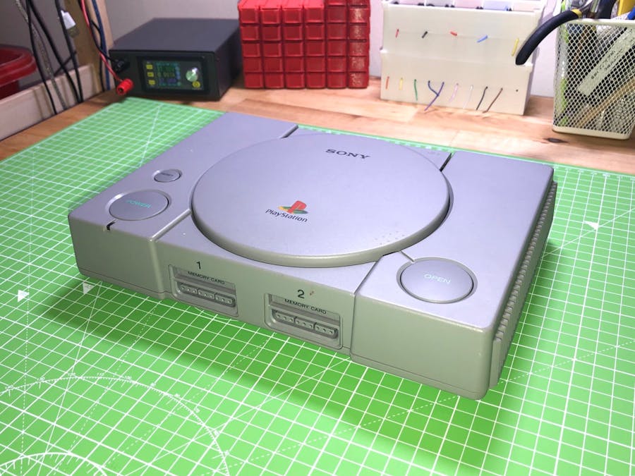
I made this a little while ago but with the impending release of the PlayStation Classic, I thought it was worth publishing my work on how I did it as I had documented things along the way. I've also posted a YouTube video showcasing what I did.
Step 1: Parts ListTo do the project justice, I was going to have to sacrifice some parts in the form of extender cables and such like.
Below is a list of the parts I used were, mostly sourced from eBay. I've included links to the ones I purchased
- Various parts for a power control circuit (to be built yet)
That is in addition to the expected parts of
- MicroSD card
- Wifi Adaptor (Optional but advised)
- Playstation controllers (Second hand ebay purchase)
- Soldering iron
I had an idea at this point of being able to desolder the rear connectors and remove the PCB which would give a nice clean look at the back.
Well it was a fine plan but in practice it was not as easy as I thought. I remember a long time ago a good friend who is far far more versed in such things that factory soldered items can be a pain to heat and remove as they typically use solder which melts at a higher temp when being factory made.
Now i'm not sure if the above is true but I was able to heat up the solder points but with only solder wick it just wasn't working. After quite a while attempting this I resorted to the brute force method, it didn't look pretty and I've shown a picture to demonstrate that.
It was even more difficult to get the multi AV and IO sockets removed. Even despite removing all the plastic tabs and carefully prising they just weren't moving so I took out a pair of plierss and gently as possible prised them out, the outside of one socket was ever so slightly damaged but it's hard to tell.
Step 3: Rear Socket ModificationAfter removing the old connectors I then set about modifying the back plate so that the sockets could sit as flush as possible, I gradually removed small parts of the back of the plastic housing so that they would site nicely behind. The panel mount USB socket came with two mounting points which were easily removed which gave a usb socket shell. I was able to gently bend these inwards to allow it to be passed through the hole and then bent them back, be very careful when bending them back out, I broke one socket by putting pressure on the centre of the USB socket.
I then mounted the HDMI socket backwards into the hole left by the Multi-AV socket and it fits in nicely, I had to mount the adaptor backwards so that it could allow the socket to sit flush with the rear of the case, I've super glued this into place but shall hot glue it place once I did out my glue gun. For now it's working nicely though so not too concerned.
You can see the internal cabling doesn't look to bad at all as they are short cables so it made routing them easier. I temporarily used one internal screw mount to mount the Pi via one of it's mounting points. This was intended to be temporary but it's quite secure so it's staying there for now.
Step 4: Game Controller PortsI dismantled the usb to PS2 connector to reveal the connectors. I also dismantled the controller sockets which are really handily in a separate module. I had read about hooking these directly up using GPIO but I thought for the sake of £1.57 the PS2 adaptor would give more flexibility.
I tried two different methods, for one port I desoldered the socket from the PS2 adaptor and on the other I mounted the wires onto the solder pads while the socket was still in place. I think if I did it again leaving the socket in place is easiest as you don't have to try and desolder while prising the socket from the board. Doing it this way you also have to apply less heat to the circuit board which is always a bonus.
As for what to connect where there are nine pins across the back of the PS2 socket adaptor and the there are also two sets of 9 pins on the back of the case controller sockets. There are a lot of solder points but they stand out as they are in a row, you can see the connections used in the picture. Just be careful to visualise which way the socket would be attached so the pins are soldered to the right points.
I'm not the greatest at soldering but it ended up ok, tinning the wires certainly helps when soldering onto an existing soldered connection.
Step 5: AssemblyAt this point it was a case of putting everything back into place and routing the cables as nicely as possible. It's not too much of a concern as there is plenty of space in the case but I didn't want it a total birds nest in there.
It's working well but I plan on updating the power to introduce a 3A power supply.


Comments
Please log in or sign up to comment.