


Hardware components | ||||||
 |
| × | 1 | |||
| × | 1 | ||||
 |
| × | 1 | |||
| × | 1 | ||||
| × | 1 | ||||
| × | 1 | ||||
 |
| × | 1 | |||
| × | 1 | ||||
| × | 1 | ||||
| × | 1 | ||||
 |
| × | 1 | |||
| × | 1 | ||||
Software apps and online services | ||||||
 |
| |||||
| ||||||
 |
| |||||
Hand tools and fabrication machines | ||||||
 |
| |||||
 |
| |||||
The moment you see the heading of “Home Automation," the first thing that comes to mind is "not another one again." I understand because, not a week passes with an email from hackster.io that someone submitted a project on home automation.
So what makes mine different? To start with, it is a concept. This home automation project takes a different approach - integrating all the automation devices into one platform. The user interface used is simple HTML5 with JQuery. This allows the user to control all the devices through a simple HTML page that can be delivered by any media - phone/tablet/desktop or any OS -Windows, MacOS. Android or Linux. By taking the web approach for user interface, the project opens up to a pleathora of controllability. For instance, usage of MQ services that let you to control anywhere in the world or Alexa/Google or similar voice controlled device to work with the devices. Though these are not currently added yet, but I will show you how it can be done in my next extension to this project.
Because of its modular construction, any addition can be treated separately. Adding a new device or adding a new room with new devices is very simple. Just add the device list to the configuration sheet, recompile the program and you are ready to go. No other changes are required. For under $100, this project is fully functional that can be used for following things:
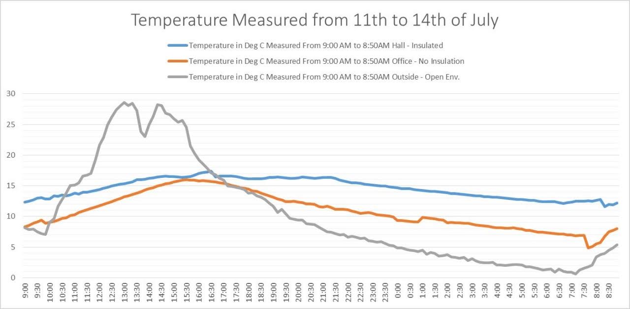
- You can record temperature in your room and outside to understand the functioning of insulation / AC
- Use a simple button to turn on /off intruder alert. This can then send an Email to you, when an intruder is detected.
- Have a Curtain controlled remotely to open or close
- Remotely Turn-on/off lights from your tablet.
All of these are currently possible and the entire device construction with a working module and programming code are provided. Raspberry Pi, Windows IoT and Node MCU consisting of ESP8266 are the major components. For temperature sensor, a Dallas Temperature Sensor is used for accurate reading. Generic HC-SR04 ultrasonic sensor is used to provide feedback of the curtain status. PIR for intruder alert, curtain, and dimmable light are your normal daily use device to which you can add current capability.
A simple but efficient concept with a working model that can be easily extended to production ready devices.
Before you start building this project, few preliminaries to be taken care of. First and foremost, let us have the programming environment setup.
Programming EnvironmentArduino IDE:
Arduino IDE can compile for NodeMCU. To do this, we need to add the board to the Arduino IDE.
- Start Arduino and open Preferences window.
- Enter
https://arduino.esp8266.com/stable/package_esp8266com_index.jsoninto Additional Board Manager URLs field. You can add multiple URLs, separating them with commas.
Now Select Tools from Arduino IDE and then Board / Board Manager. Look for ESP8266 and add it to the IDE.
Next for temperature sensor, we need to add two libraries to IDE and for ultrasonic we need to add two more libraries. Library additions are as follows:
Click on Sketch and then select Include Library/ Add.ZIP Library...
In the ensuing dialog box add the following libraries: (Note: version nos / file name may have changed)
Library: NewPing for UltraSonic Sensor
File Name: NewPing_v1.9.1.zip
Link: https://bitbucket.org/teckel12/arduino-new-ping/wiki/Home
Library: Temperature Sensor
File Name: Arduino-Temperature-Control-Library-master.zip
Link: https://github.com/milesburton/Arduino-Temperature-Control-Library
Library: Library for Dallas/Maxim 1-Wire Chips
File Name: OneWire-master.zip
Link: https://github.com/PaulStoffregen/OneWire
Visual Studio IDE:
In the Visual Studio, you need to add reference for Lightbuzz.smtp. This can be accomplished by selecting Tools in the VisualStudio IDE and then select “NuGet Package Manager/Package Manager Console”. In the console window at the bottom, type the following:
PM>Install-Package lightbuzz-smtpDetails can be found at: https://github.com/LightBuzz/SMTP-WinRT
Windows OS:
For windows 10 you need a CP210x USB to UART BridgeVCP Drivers. This will install your USB as Serial port which Arduino IDE can use and communicate with microcontrollers. The details can be found here:
https://www.silabs.com/products/development-tools/software/usb-to-uart-bridge-vcp-drivers
That’s it. The environment for building the code is now complete. You are ready to compile the code. Before you do that, some configuration changes.
Configuration SetupDevice Configuration:
You need to provide various WiFi settings. IPAddresses and UDP ports can be used the same, if your network falls under the same subnet. Let us look to the changes to the devices. All devices uses NodeMCU built on ESP8266 chip. A great network board for hobbyist. This board can be programmed through Arduino IDE and uploaded to the module via USBport. Let us look at the configuration changes required.
Each NodeMCU device code in Arduino IDE are in separate folders, typically named with “Remote …..” and program code extensions are.ino. Open each of the files (four of them) and change the following in thecode:
const char* ssid="SSID"; //type your SSID here
const char* password = "password"; //Type your Password here
For RemoteIntruderDetect and RemoteTemperatureMonitor two more changes are required:
const unsigned int RemoteUdp = 51000; //If you prefer, you can leave this as – is.
const IPAddress RemoteIP = IPAddress(192,168,0,175); // This is the Raspberry Piaddress. Use the appropriate one
For RemoteUDPControlledSinglePhaseMotor the curtain distance needs to be properly measured. Once done ensure the following parameters are changed.
#define MIN 5 //Closed distance
#define MAX 90 //Opened distance
This must be reflected in the CurtainMaxDistancesand CurtainMinDistance defined in next section.
Note: If you have changed the Port address then ensure you use the same port address for “LISTENPORT = " in the next section
Rest ofthe code, you can leave it as is. Compile each of the code and upload it to your NodeMCU, through USB.
Home Automation Program Configuration:
To make things easier, all the configurations are in one file, Constants.cs. Important parts that need changes are given below:
namespace HomeAutomation
{
static class Constants
{
//General Constants
public const int ROOMS = 3; //Change dependingupon your implementation
public const string EMAILADDRESS = "yourname@gmail.com"; //Change to yourEmail
//SocketsServices Constants for various Hosts. Change or leave as-is.
public const string CURTAINSOCKET = "4210";
public const string DIMMERSOCKET = "5210";
public const string INTRUDERSOCKET = "8210";
public const string TEMPSOCKET = "7210";
public const string LISTENPORT = "51000";
//Web ServicesConstants
public const string SOCKET = "8090"; //Listening socket for Web Front
public const string UDPSOCKET = "30285";
public const int BUFFERSIZE = 8192;
//IPAddressConstants you can use the same if you have the same subnet. Else changeaccordingly
public static string[] CurtainAddress = { "192.168.0.152", "192.168.0.151", "192.168.0.153" };
public static string[] DimmerAddress = { "192.168.0.160", "192.168.0.161", "192.168.0.162" };
//IP Address Constants used by ListenSocket Services. We will keep the sockets the same.
//Used by Temperature control and Intruder Detector
public static string[] IntruderDetectAddress = { "192.168.0.191", "192.168.0.192", "192.168.0.193" };
public static string[] TemperatureMonitorAddress = { "192.168.0.181", "192.168.0.182", "192.168.0.183" };
//Curtaindistances that vary with window / room in cm.
public static int[]CurtainMaxDistances = { 90, 120, 150 };
public static int[] CurtainMinDistance = { 5, 3, 1 };
.
.
.
.
}
}
Note: Current implementation is coded for 3 rooms only as the slider control provided in the UI is for 3. However the Temperature monitor buttons and Intruder Alert buttons are for 6 in nos. So more than 3 rooms can be implemented. If you are implementing for more than 3 rooms, just change the room nos. In the UI design, I will show you how to easily add the buttons in the next section.
For UDP Sockets ports I have provided here are chosen arbitrarily. If you want to use different nos., please feel free to use anywhere from 1000 to 65000 as long as it does not conflict with other sockets. (For instance 8080 is used by Windows IoT Device Portal). However you need to ensure the “unsigned int localUdpPort =” in the appropriate device must reflect this.
UI DesignThis is a simple HTML Web page using JQuery. The three parts of the web pages are provide under the folder webpages. These files are body.html, header.html and theme.css. If you want to add more sliders for instance, then just copy and paste and increment the id no in body.html file. No other changes are required. That’s it. For instance to add more slider then copy previous line, paste and increment the id no. (only change is id=”SliderB3”)
<p>Dimmer1: <input class="sldrclass" id="SliderB3" type="range" min="0" max="100" step="25" value="0" /><span class="sltxt">0</span></p>at the end of the line:
<p>Dimmer1: <input class="sldrclass" id="SliderB2" type="range" min="0" max="100" step="25" value="0" /><span class="sltxt">0</span></p>header.html consists of scripts in Jquery while theme.css is the css file. If you are conversant with the HTML5, CSS, Jquery or Javascripts, feel free to edit to your requirements. The program code will assemble all these files and present it as one HTML file. Thus the UI design can be edited separately.
You are ready to compile the program. The next part is the hardware.
Hardware ImplementationComputer and OS:
Microsoft Windows IOT is the OS of choice. It is lightweight and easy to install as headless OS on Raspberry pi. Apparently Raspberry Pi is the computer hardware. I will not go deep into installing this, as Web is full of videos on the installation. Use the latest Pi, and updated windows.
Device ImplementationBy using readymade modules, I have made building and implementing the devices at ease. Some soldering experience and handling the multimeter to ensure correct connectivity, you can build all the devices. We will look into each of them.
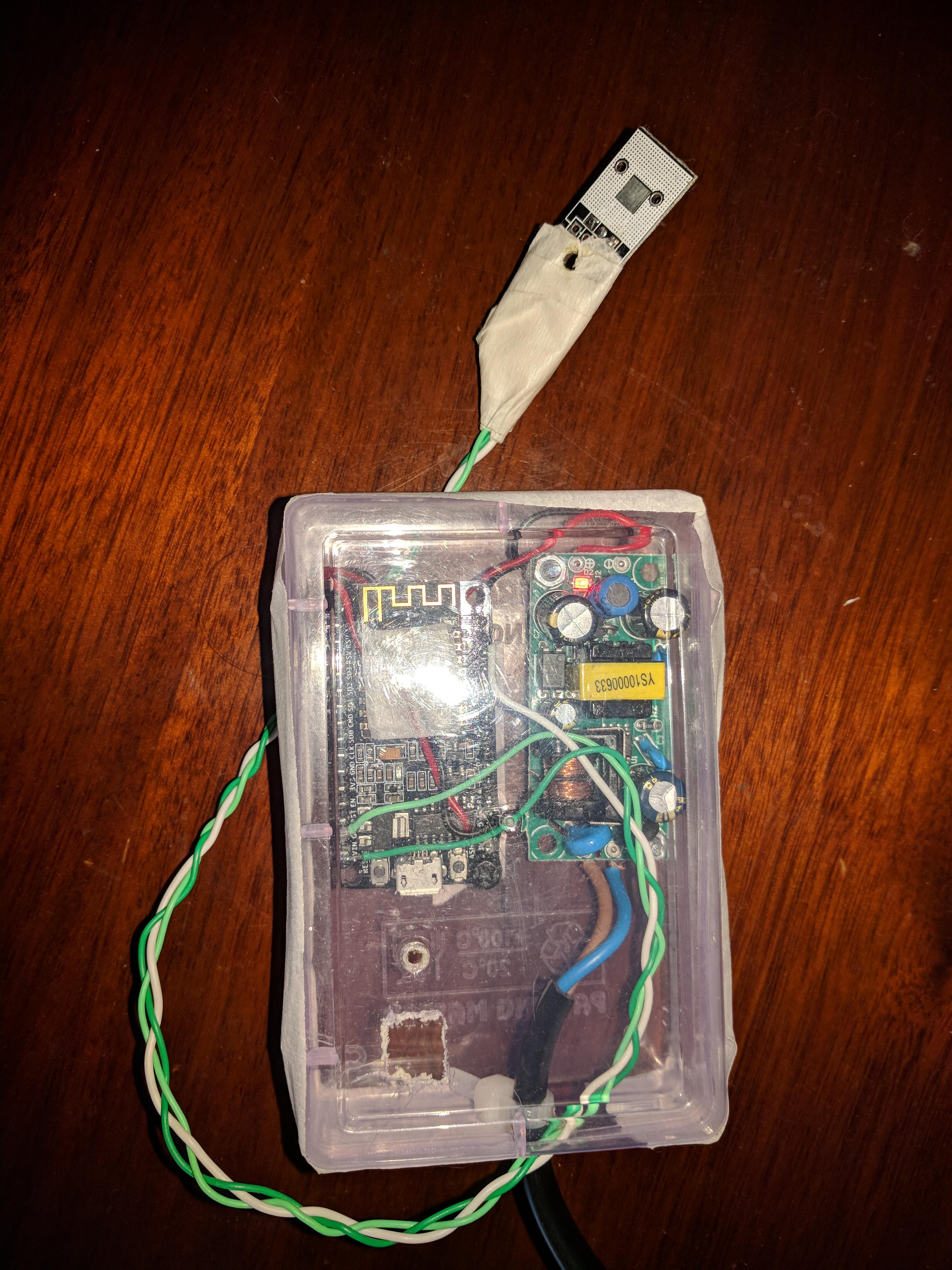
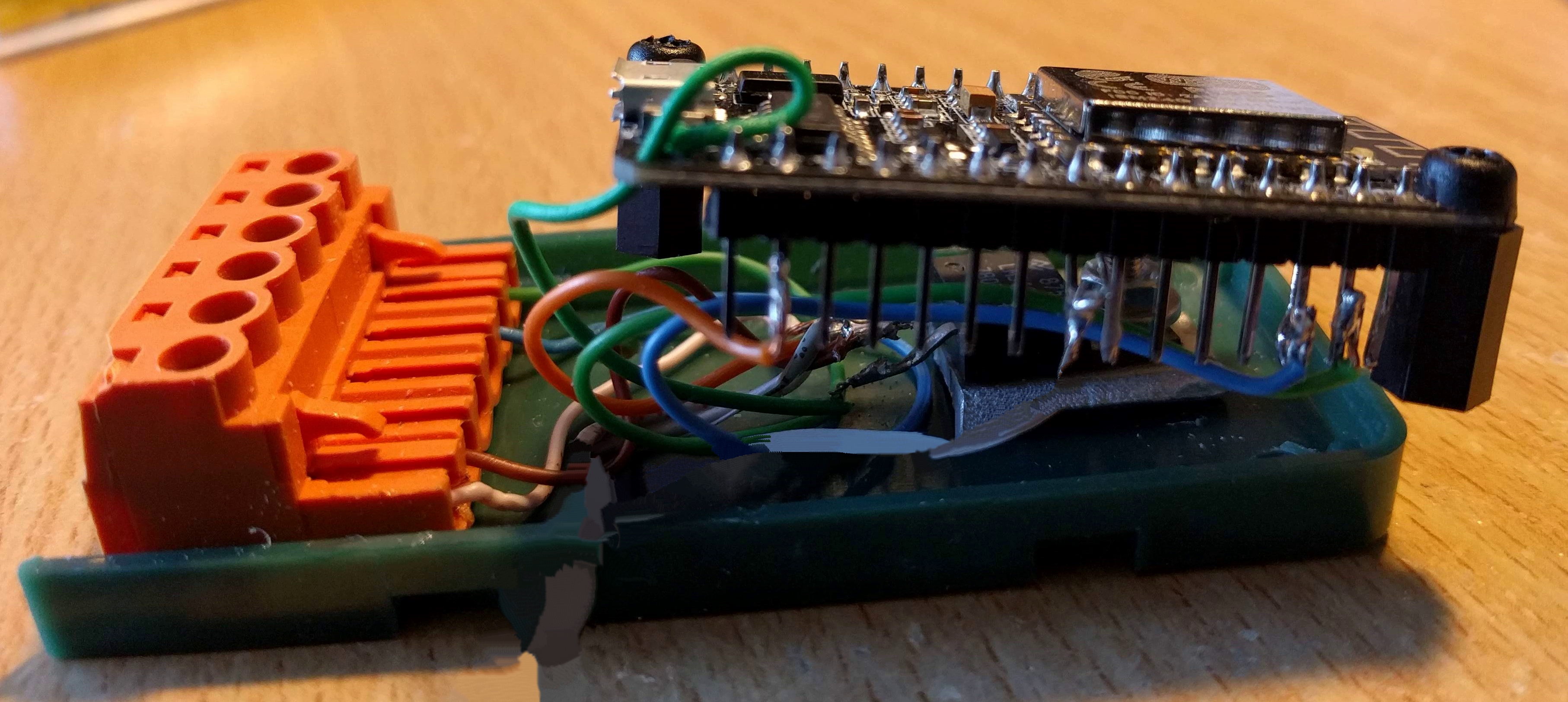
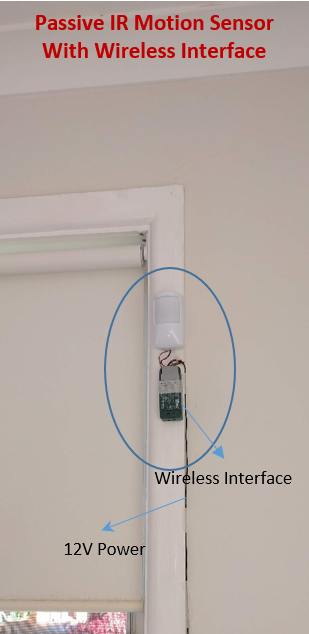
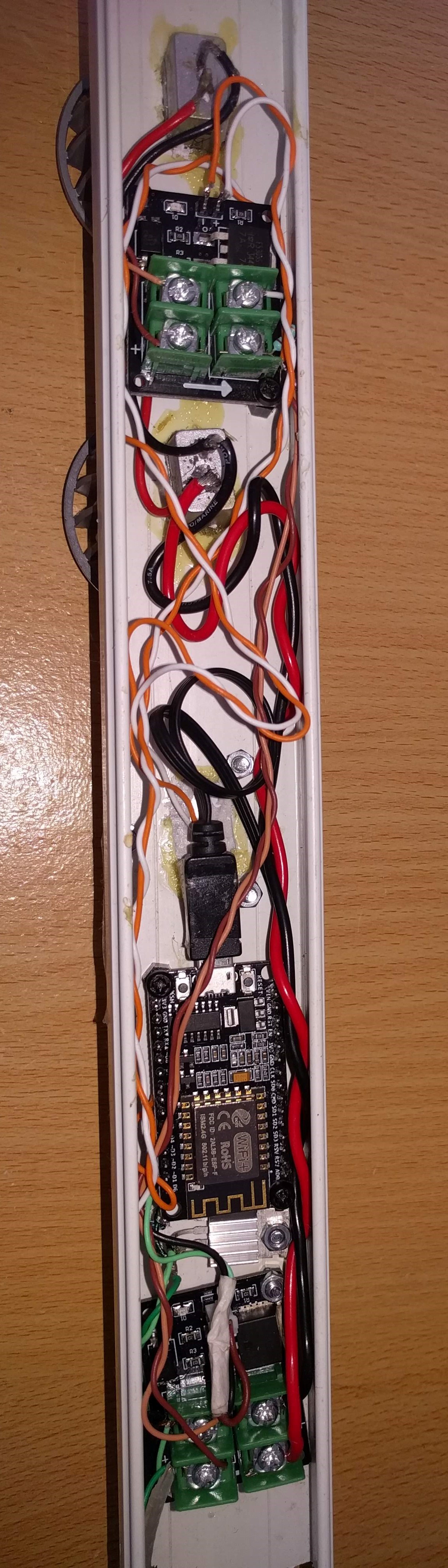
Intruder Alert:
Obviously very easy one. Only two ports D1 & D2 appropriately named as SEND and RECV of NodeMCU are used. (There is a TRANSMIT Port D5 defined and a 4K pulse is sent through this. This is for testing and is not used for this project.) The PIR I use is a Honeywell device which has a closed loop or lower resistance between the two Trigger points under normal condition and has high resistance or open condition when intruder is detected. Connect a 4K7 (pull-up) resistor between D2 and 3V3 power supply. D1 and D2 are connected to your PIR Trigger points. To power the NodeMCU use the regulator 7805. PIR uses 12V supply and we can connect the 7805 input to the 12V and the output 5V to the NodeMCU. Put all this in a small box as shown in the picture and youare ready to go.
Note: (TRANSMIT and a 4K pulse burst in the code is used fora RF transmitter which is received by a RF receiver near the Honeywell monitor base. RF receiver latches a relay which opens or closes the circuit for the base. If you need such elaborate setup, you can use the same. Write to me on details of connections.)
Temperature Sensor:
NodeMCU and DallasTemperature sensor DS18B20 are used. D1 is used as wire bus through which DS18B20 communicates to NodeMCU. DS18B20 itself has only 3 pins: Vcc, Output, and Gnd. Vcc can be connected to Vin, Gnd to Ground and the output to D1 on NodeMCU. No more connections required. I have used a Power supply module to provide stable 5V-1A supply. Total power consumption though is just under 45mA@ 5V.
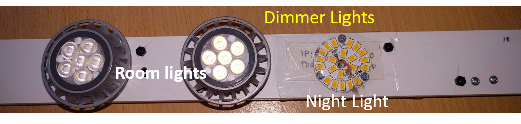
Light Dimmer:
There is hardly any soldering here. I had a requirement for room lighting and night lighting. Hence, I have used one NodeMCU to control both the lights, with a night flag. Use 1 Khz PWM to feed the light. This allows us to control the brightness. Port D3 is used for Normal lighting and D2 for Night lighting both configured as PWM ports and used for +ve terminal of Opto-coupler. D1 and D5 are used for the –ve terminal of Opto-coupler. Thus you get isolation from 12V and isolation from high current flowing in LED to NodeMCU, which operates at 3.3V. The – and + terminals marked on the board are for Opto-coupler input voltage. D3 & D1 are connected to one of this board and D5 & D2 for another board. These control Normal Room lighting and Night lighting respectively.
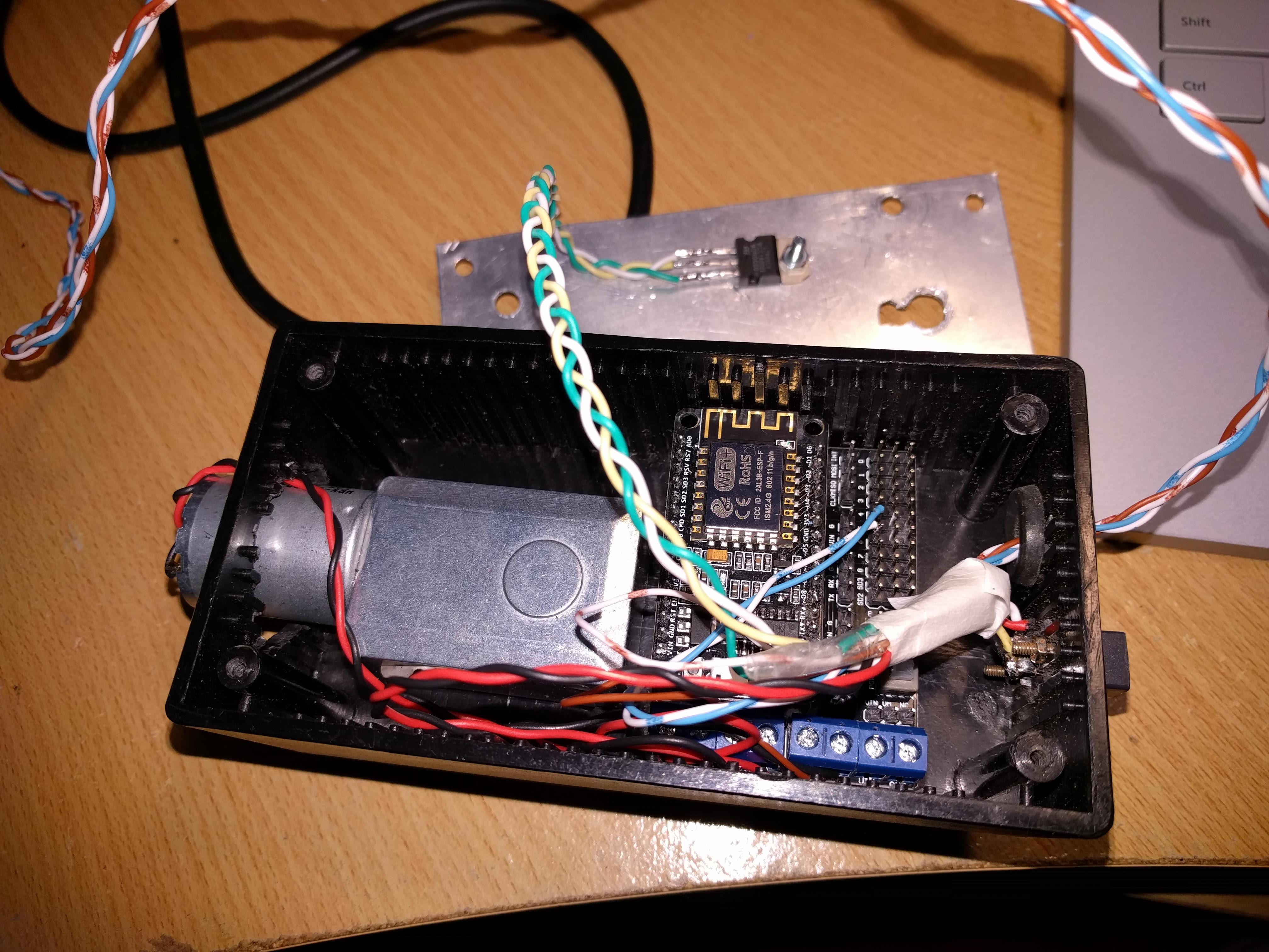
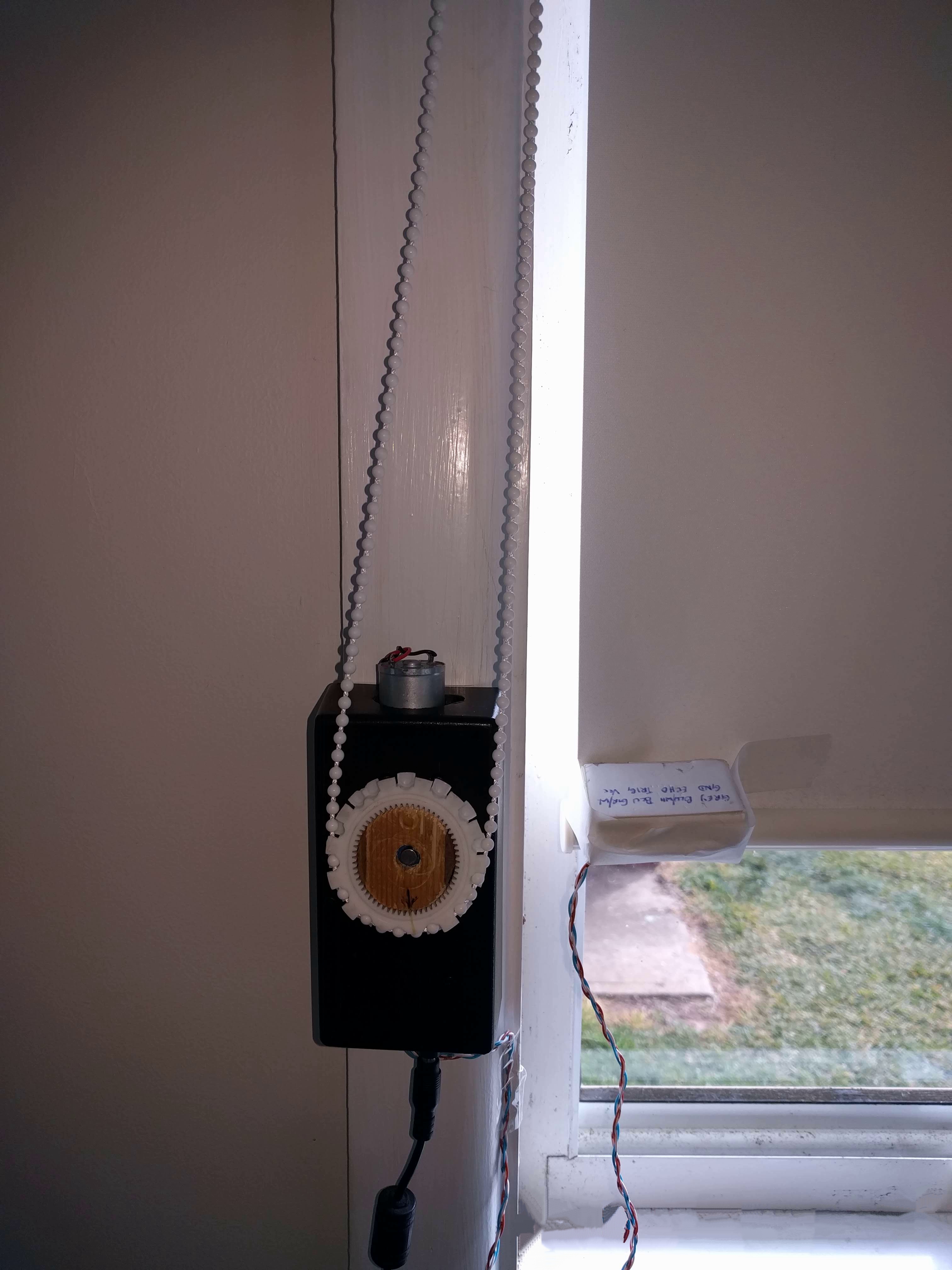
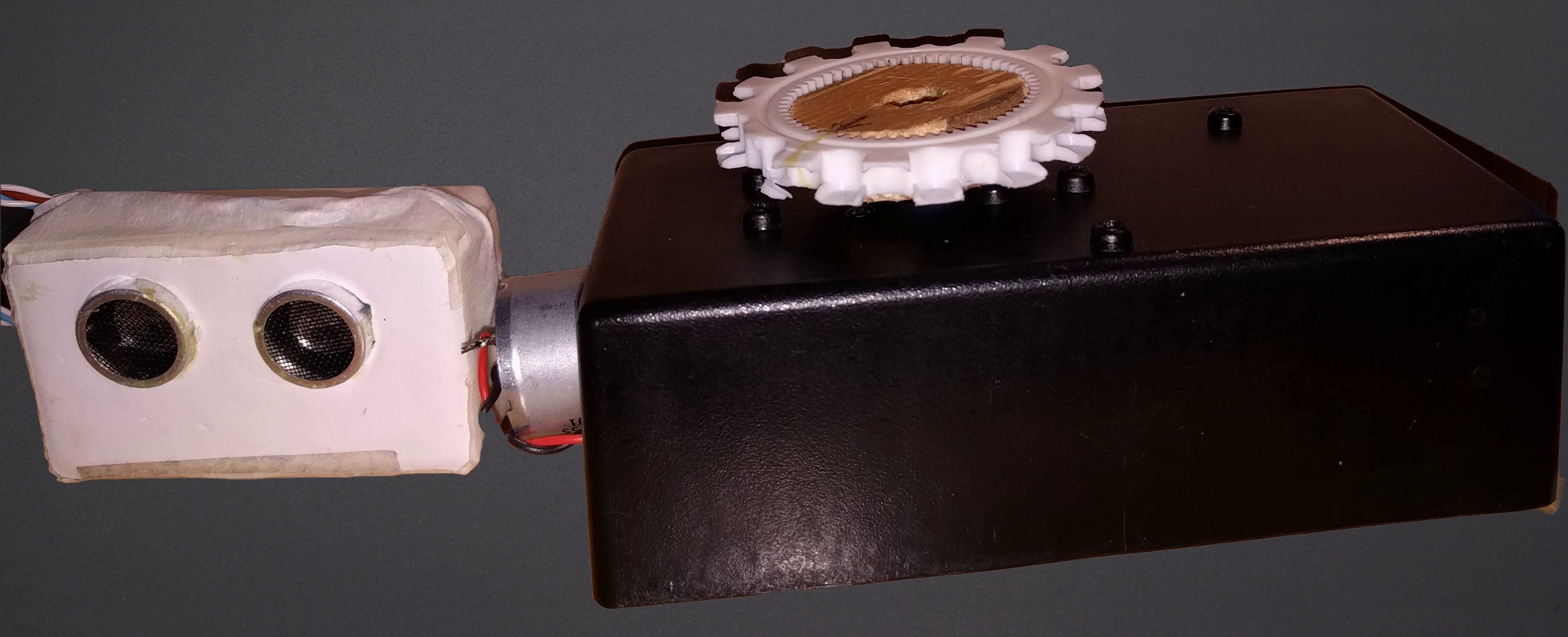
Curtain Motor Controller:
For the curtain motor, we use a special motor drive expansion board (motor shield) for NodeMCU. D1 is used as PWM port and D3 used for direction. By making D3 High or low we can make the motor run clock-wise or counter clock-wise. As all these are internally connected, there is nothing much to do. The motor itself is a single phase motor. PWM controls the speed of motor, but coded as maximum. You can change this as per your requirement. Output ports for motor are A+ and A-.
To ensure the curtain motor doesn’t get over run, ultrasonic sensor is used, connected to curtain. The sensor measures the distance from the ledge and using MIN and MAX variable stops the motor when either of the condition is reached. The sensor also used when you want to open the curtain partially. This is accomplished by sending a string “Set Distance=xx” where xx is the distance from the ledge. NodeMCU and the Ultra Sonic Sensor are powered by 5V 7805 Voltage Regulator - the input of the regulator is connected to 12V supply.
This completes the project. Once all the programs are compiled and loaded to the devices, they can be installed in their respective locations. Devices will automatically start the program and connect to your WiFi devices and it is ready to receive commands from Pi. The main code for Raspberry pi can be compiled and deployed from Visual Studio. You must select ARM processor for compiling. Once everything is done start the program in Raspberry pi. If the program compiled correctly and the IP address are correct then open up your browser and type the following URL:
If your Raspberry Pi address is different and if you have changed the Port no., then use the appropriate address and Port. You should get the following screen:
Depending upon no.of devices you have connected, you should be able to control each of them. You can click on Diagnostic Channel or Log to a file to see any diagnostic information. If Record Temperature is clicked you will get the Temperature updated every 10 minutes to a file.
If you do not get the screen or if you cannot control any ofthe devices, do not fret. Go through the document which highlights all the changes. Ensure you have followed each and every one of them. As for devices, test one device at a time. If you still have issues, please feel free to contact me. I can sort this out.
The interface is self-explanatory. Curtain control and Light Dimmers are defined for 3 rooms while Temperature sensors and Intruder Detection are defined for 6 rooms. Intruder and Temperature Monitor provides visual feedback. Every action if the server acknowledges are reported at the bottom of the screen “ServerReturned:".
This project by no means is complete. A lot of additions are possible. Most important ones are tabled below:
Simple Configuration File: It is not always possible to compile the program everytime something changes. The entire configuration must be stored in a local file that can be easily edited.
Persistent Storage. All variables are currently volatile stored in Pi. If Pi reboots then the device status will not be in sync with the UI.
Heartbeat: Every network Engineer will know about SNMP and MIBs. These are heartbeat pulse that needs to be monitored across all network devices. This will give us the status of each device.
Voice Control: Since all the devices are on network, it will be easy to interface this with Alexa.
MQ & Cloud: Messages can be queued through cloud. Thus the devices in the network can be controlled through web, instead of home network.
Many more addition of devices are possible.
If you like this project, please provide your comment.
Thanks for browsing!
Temperature Sensor
Temperature recorded over 3 days in Richmond, NSW Australia

Intruder Alert Dis-assembled
Intruder Alert fully assembled


Comments