While going through the educational site for Lego Mindstorm NXT projects for my grand-daughters, I came across this website: http://www.nxtprograms.com/index1.html
Impressed by the 3 Speed Transmission with Clutch model, I decided to construct one. The model itself provides a 3 speed Gear train controlled manually by pulling levers for gear and clutch mechanism. The Accelerator is a very simple switch that only provides a software simulation of accelerating the speed to max. This provided a good way to teach kids on gear transmission, use of clutch etc. The basic model is provided below:
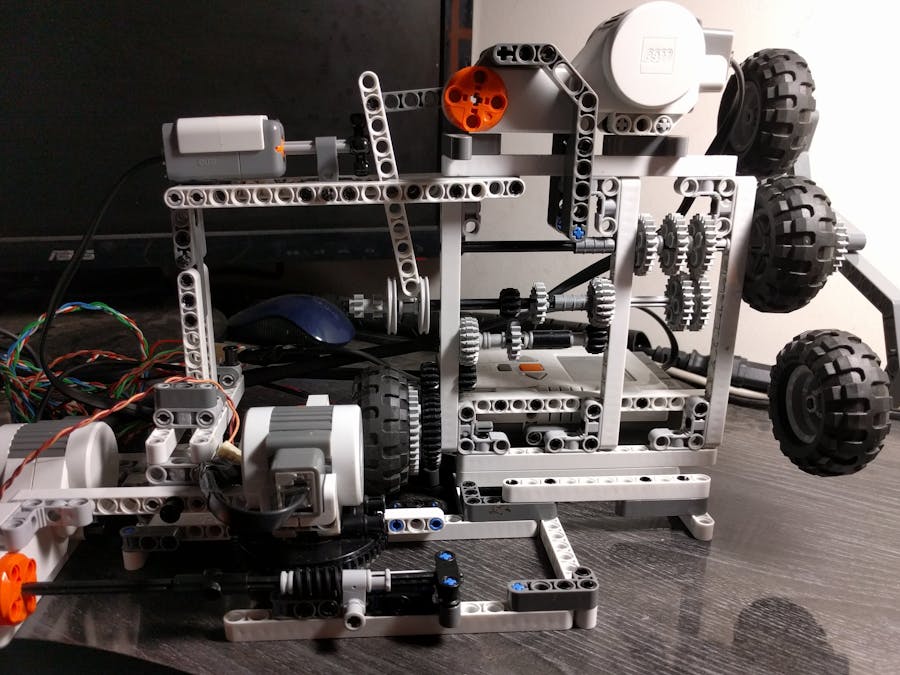
With a new found passion for Raspberry Pi, I decided to give this model a complete makeover by changing the manual transmissions to “Fly-by-wire” technology. This gives us the ability to control this through a computer. So manual controls were replaced with Motors for Gear changing and Clutch control. Accelerator is replaced with a software controlled Slider and an Index switch was added to keep track of current running Gears. Resultant modified model is provided below:
The completed project with the Raspberry Pi connected:
Now the next thing is to add a proper interface to connect to this setup. For this Windows IoT running on Pi was chosen. In addition, to control this from Internet, a separate Windows based program for controls was written. While the Transmission can be controlled locally, with the additional program, the user has the option of control through the Internet.
The screen for windows IoT is given below:
The optional Windows Controller to control through web is:
The controls on both the images are self-explanatory. The status texts provide IoT Hub messages. Microsoft IoT hub is used for message queue requirement for this project. In addition to Manual gear changes (through existing buttons of course), the transmission could be put on “Auto”. With “Auto” mode selected, the gear trains will automatically switch gears depending upon the speed (Rev Power- Slider control).
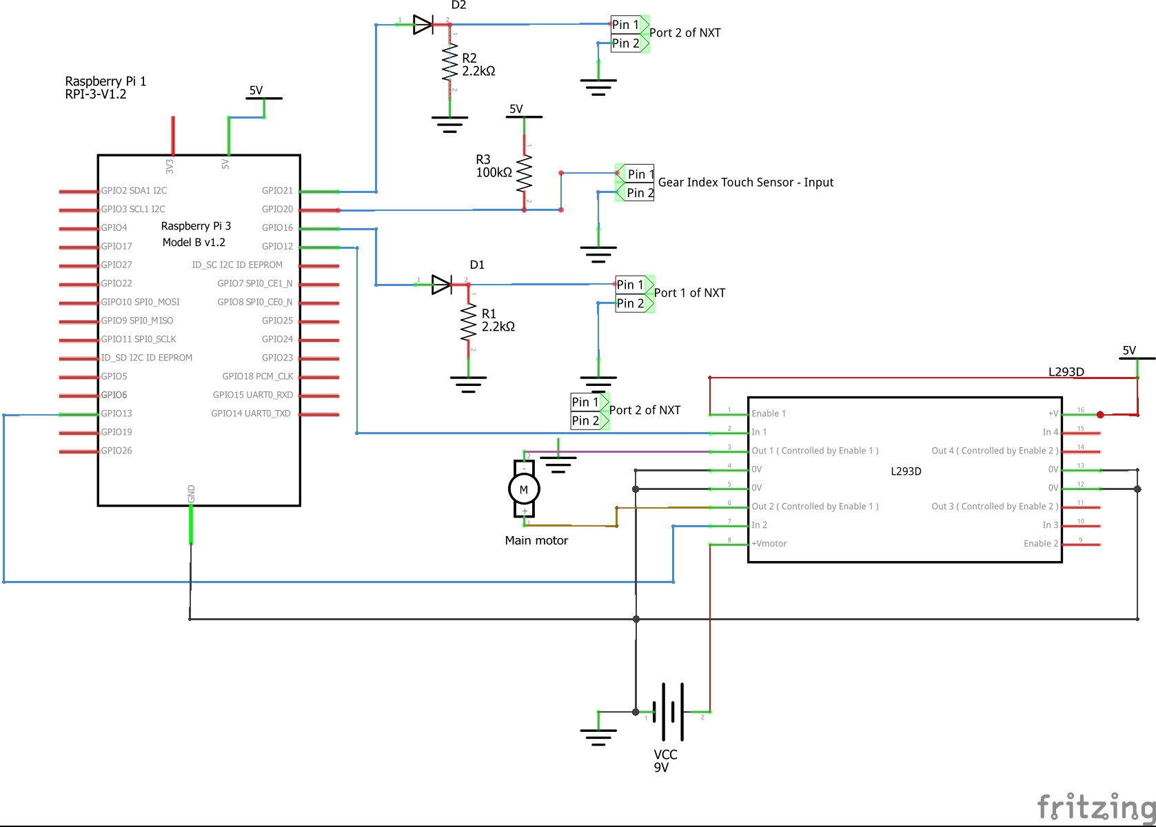
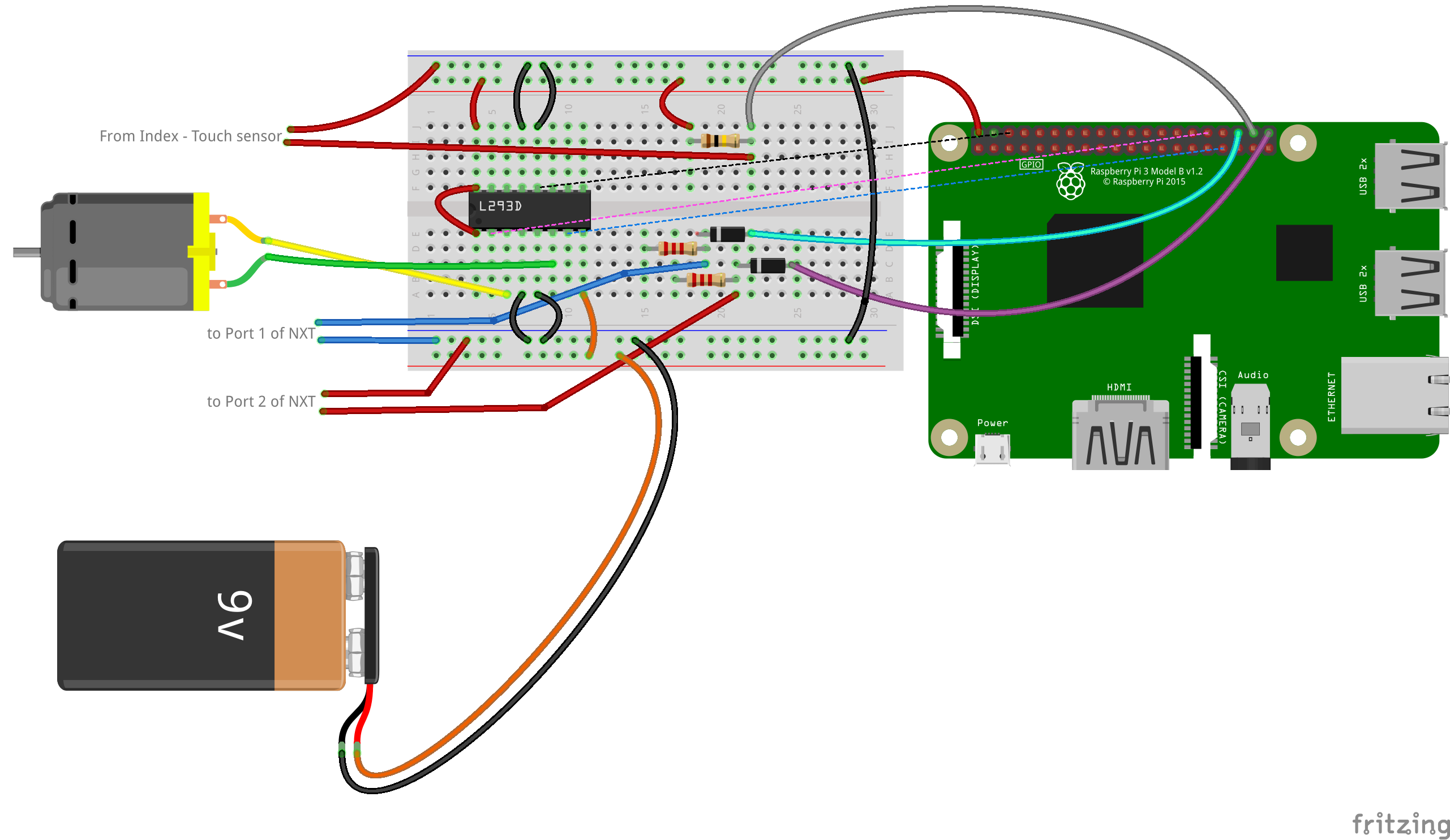
Main MotorRaspberry Pi is used to drive the main motor. This gives us the ability to control the speed of the motor with a slider control. To control the motor Pulse Width Modulation (PWM) is used. Windows IoT is switched to Lightning DMA mapped driver to make use of hardware PWM. A simple H-Bridge Motor controller is used to interface the PWM to Motor. Also since the motor draws 9V which the Pi cannot provide, L293D dual H-Bridge IC is used to drive the motor. The width of the pulse itself is controlled by the "Slider Control", thus providing variable power to the motor.
Gear Shift MotorFor shifting gears, accuracy is required to a precision of 1 degree. Hence NXT itself is used to control the rotation. The Gear Shift Motor is connected to Port B of the NXT brick. For every 90 degrees turn of Gear Motor, Transmission is shifted to next gear. Thus if we start at Gear 1, a 90 degrees turn will shift the gear to 2 and another 90 degrees to Gear 3. The Gear Motor would by now rotated to 180 degrees. We can either retrace back to Gear 1 by reversing the motor or move forward by another 180 degrees to get a full circle. The Gears will be thus shifted as 1 - 2 - 3 - 2 - 1. The motor itself is switched-on by the Pi by providing a High pulse to the input Port 1 of NXT. When this is detected by the NXT, a 90 degrees rotation is provided.
Clutch MotorBefore the gear shift motor is engaged, the clutch motor is activated. This is connected to Port A of NXT Brick. This rotates to 180 degrees, which rotates a swivel base through worm gear. The Clutch motor is mounted on this swivel base and hence turns adequately to disengage the motor from the Transmission. Then the gear shift motor is activated. When the gear shift motor completes its process, the clutch motor reverses back to original position. The entire process of clutch motor and gear shift motor operation is handled by NXT program.
Reversing Gear ShiftThough the Gear Shift can work full circle using the above strategy of 90 degrees rotation per Gear shift, occasionally proper synchronization of the gear becomes tedious. Also when you want to shift the gears backward, say for example shifting from 1 to 2 and then 2 to 1, using just the forward motion, you will have to engage the gears thrice, before getting back to 1. To solve this problem, the gear shift motor itself can be rotated backwards if needed. To do this an high pulse is sent to Input Port 2 of NXT. Program running in NXT on detecting this pulse, will reverse the gear shift motor thereby effectively shifting the transmission backwards.
Index SwitchThe Pi program has to keep track of current Gears that the transmission is using in order to decide, when to reverse the Gear Shift motor. More useful when "Auto" Mode is used for transmission. Typically “Light Sensor” will do this job. However I used a switch (Touch Sensor) for this purpose. The output from the switch is read by the Pi and then resets the Gear variable to 1 when this switch is pressed. The Boolean GearMovement is also set to true.
Note: If GearMovement is false, then the gears are engaged in reverse.
Transmission ModeTwo modes are provided, with "Manual" mode as default. In "Manual" mode the user controls shifting of gears. In "Auto" mode, depending upon the speed, the Gears are automatically changed.
Internet ConnectivityTo make the project more interesting, I have included a small Windows based program to control the Transmission through Internet. For this Microsoft IoT hub is used. On startup Raspberry Pi registers itself with the IoT hub as an IoT device. A status message provides whether the connection has happened successfully. Once connected, the user can check the "Internet Connection" "Check Box", after which the application is ready to receive information from the net.
Windows client, will send messages to the IoT Hub using AMQP (Asynchronous Message Queue Protocol). Depending upon what button is pressed, appropriate message is sent. This is then decoded by the IoT device and then acted upon.
Working DemoA working Demo of the project can be found in YouTube:


Comments
Please log in or sign up to comment.