What is it?
Features:
- An Arduboy clone using SSD1306 SPI OLED and Arduboy Pro Micro in a MSX cartridge form factor.
- Compatible with existing Arduboy pre-compiled games.
- Arduboy control using a joystick through MSX (via this cartridge's hardware and software) without software modification of existing games.
- I2C communication for data and control between Arduboy and MSX for creating new enhanced games.
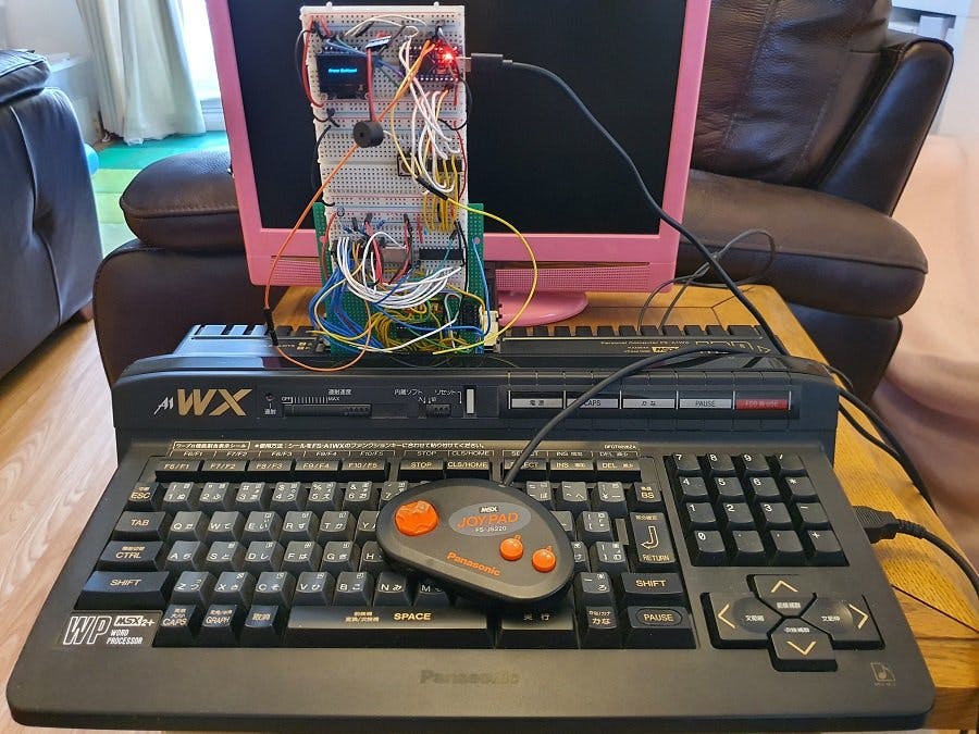
This is a project to make an Arduboy clone on an MSX cartridge. It is intended to be used by inserting it into a MSX computer (a retro microcomputer from 1980s) to integrate Arduboy hardware into the MSX. This Arduboy does not have the controller buttons on the board, but by using the joystick (directions and 2 buttons) connected to the MSX, it controls the Arduboy button presses through software and hardware.
To maximise software compatibility with the currently available library of compiled games for the official Arduboy, the project uses a SSD1306 OLED similar to the official Arduboy, and an Arduino Pro Micro which has the same ATmega32U4 chip.
There is no Arduboy code change necessary to make the joystick control work, so all Arduboy games should work.
In order to make the MSX to Arduboy integration deeper than just joystick controls, this project also includes an I2C connection between the Arduboy and the MSX for serial communication using an I2C chip (PCF8584). Currently the I2C chip and the software is setup to have MSX as a I2C master, and Arduboy as a I2C slave. But it is possible to make it the other way round in software. The Arduboy2 library disables the I2C pins on the Arduino, so that part of the code has to be commented out in order to utilise the pins for the I2C. This is the only change necessary from the normal Arduboy for any software to be developed for this cartridge that would want to use I2C to transfer data/control MSX to/from Arduboy.
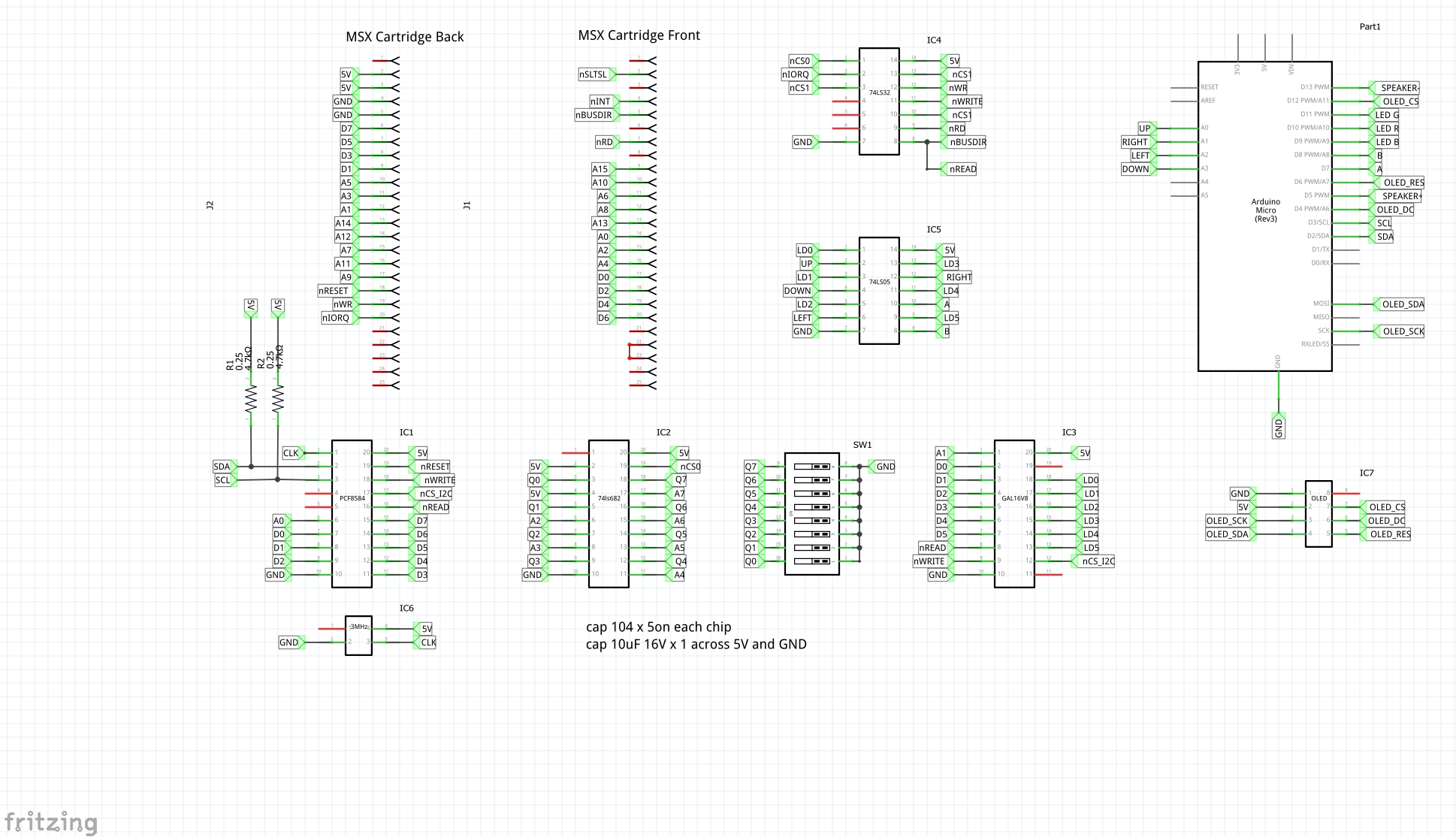
Overview of the designAn MSX cartridge was assembled on a prototyping board with 50 pin edge connector with the components listed in the Things according to the design shown in the schematics. A few small bread board is placed on the top part of the cartridge to place the OLED display, the Arduino PRO MICRO, and other chips that were not soldered onto the board.
For the joystick control, a MSX program (joystick.c) to read the joystick and send the status of the buttons out of MSX IOPORT address 0x06 was written. (The IOPORT addresses can be changed on the board set by the DIP switches and by making matching changes in the software). The address is decoded by 74LS682, and appropriate read/write/chip select and bus control signals are generated by 74LS32 and GAL16V8). The UP, DOWN, LEFT, RIGHT, A and B button states (1 is on) are the 6 bits to be sent (LSB bit 0 is UP, bit 1 is DOWN, bit 3 is LEFT etc) through this IOPORT. The GAL chip's Cupl code (ARDUBOY.PLD) was written in WinCupl for GAL16V8. The button states go through 74LS05 open collector chip connected to pins for the buttons on the Arduino to simulate the button presses. The Arduboy clone part is a standard setup with PRO MICRO and SSD1306 OLED SPI screen chosen for maximum compatibility with the pre-compiled Arduboy games.
For the I2C communication part, the 8 bit IOPORT data is received by PCF8584 I2C chip to do the I2C communication with the Arduino. The same address decoding process also produces the chip select logic for PCF8584 from GAL16V8. The MSX IOPORT address 0x04 and 0x05 are used for talking to the PCF8584 to do I2C communication. For demonstration of the I2C communication between the MSX and Arduboy, a demo sketch (Arduboy_HelloWorld.ino) and a MSX program (helloi2c.c) was written.
How to use- Playing a normal Arduboy game
Flash the Arduboy using a normal method.
Insert the Arduboy cartridge into the MSX computer's cartridge slot when the machine is off.
Switch on the MSX. On the MSX-DOS prompt, load the joystick.com program from the disk (just type joystick and press return key). Play the game using a joystick connected to MSX joystick port 1.
- Running the I2C demo
Compile and send Arduboy_HelloWorld.ino to the Arduboy (see the following section on programming the Arduboy for a small library change). Run helloi2c.com in MSX-DOS. Move the message displayed on the OLED screen by pressing the joystick directions.
To demonstrate master receive and button presses, when button B is pressed, MSX will request to receive the Y coordinate of the message from Arduboy. Arduboy sends back via I2C the coordinate value, and it is displayed on the MSX screen.
To demonstrate master send, when button A is pressed, MSX will wait for input from the user on the MSX keyboard for a string to change the message. After the new message is typed in, it is sent to Arduboy via I2C, and the OLED display will show the updated message.
Sometimes the Arduboy's OLED screen is all white. This happens as some keys got registered as pressed when powering up the cartridge. The joystick program can clear the button state in the beginning, so just press reset on the Arduino after the program is executed. (Some key presses when resetting the Arduboy does things, like white screen or turn off sound.)
- Programming the Arduboy
There is nothing special or something need to be done differently on the Arduino code to make the joystick input work. But to use the I2C feature, the I2C needs to be enabled on the Arduino (disabled by Arduboy library). To make this change, find the Arduboy2Core.cpp file (make sure it is the one used in the build path. There may be one in the libraries folder and another in the user folder's AppData area), find the line that calls bootPowerSaving() and comment it out ("//bootPowerSaving();").
For programming the Arduboy in Arduino, see the Arduboy_HelloWorld.ino example. It just uses the Wire library (Wire.h) as normal I2C programming. In the Setup(), the Wire is setup with 90KHz clock to match the chip on the MSX side, and the slave address is 1, this is seen as address 2 or 3 on MSX side as the chip is 7bit address plus 1 bit for Read or Write flag (00000010 or 00000011). The arrangement is that the MSX side is I2C master and the Arduino side is the I2C slave, so the events for Wire.onReceive(receiveEvent) an Wire.onRequest(requestEvent) are registered. Program the read routines in the receiveEvent(), and write routines in the requestEvent(). As Arduino is the slave, it can only respond to these events. It is possible to make the Arduino I2C a master, and MSX a slave, in that case, the code on the MSX side will need to be modified.
- Programming the MSX
See the helloi2c.c example (the joystick reading and sending to Arduboy code is the same as in the joystick.c file). It is not recommended to change the joystick routines. Just to explain here what it does, the port to send the button states to Arduboy (through some other chips) is the IO port assigned to IOPORTC in the code (address 0x06). The UP, DOWN, LEFT, RIGHT, A and B button states (1 is on) are the 6 bits to be sent (LSB bit 0 is UP, bit 1 is DOWN, bit 3 is LEFT etc).
For I2C programming, at low level, the IOPORT0 (address 0x04) and IOPORT1 (address 0x05) are used to talk to the PCF8584 to control and send or receive I2C data. These are used in the pcf8584_init(), pcf8584_master_send() and pcf8584_master_receive() functions, so just use these functions to program.
It is possible to extend the provided code (the PCF8584 drivers), with more status register check and error handling routines, I2C speed, I2C slave mode etc. See the data sheet for PCF8584 for the features of the chip.
- Notes on power supply:
There are a few ways you can wire to power the Arduino Pro Micro on this cartridge, depending on whether you want the USB connected or not, and it also depends on the quality of the clone Pro Micro boards as well in terms of parts used and its design. The MSX cartridge slot has 12V, so that could be used to feed the RAW PIN in theory, but it is possible the power regulator on the board might be using an inferior parts compared to a real Arduino.
When flashing a new game on the Arduino Pro Micro, do it with MSX switched off.
MSX is a trade mark of the current legal holder.
All software and development tools used are legally and readily available on the owners site and suitable for the development of this project.
For MSX 50 pin edge connector, I have based it on Apple II card edge connector from user vanepp (Peter Van Epp) from fritzing forum:
apple2_edge_connector.fzz
https://forum.fritzing.org/t/how-do-i-create-a-pcb-with-an-edge-card-connector/5085/18
I take no responsibility for any damage caused to anyone/thing by using this hardware/software.


Comments
Please log in or sign up to comment.