


Hardware components | ||||||
_ztBMuBhMHo.jpg?auto=compress%2Cformat&w=48&h=48&fit=fill&bg=ffffff) |
| × | 1 | |||
 |
| × | 1 | |||
 |
| × | 1 | |||
 |
| × | 1 | |||
 |
| × | 1 | |||
 |
| × | 1 | |||
This spans a way back but when a game called Overwatch was first released, I remember seeing a video where your keyboard could light up based on what was going on in the game. Seeing hardware and software work together, even if it was mostly a gimmick, was pretty interesting and I've wanted one of those fancy keyboards since then.
Well, I still haven't gotten one, and I'm not sure I plan to. What I do have though, is an Arduino and some LEDs. My laptop stand does have a gap under it so I thought I could chuck some lights under there and see where programming could take me.
HOW IT WORKSI chose to make my LEDs react to the game Genshin Impact. You have a party of four characters that engage in combat. Each character has an ultimate move that charges up over time, where the indicator at the bottom right of the screen glows when it's ready. The plan was to turn on the LED when the ult was up, for each of the characters. There are 7 different elements in the game that each character belongs to, so I opted to set the LED to a matching colour.
Template matching is applicable to everything so I'll run through this tutorial (..I hope) with my game as an example and you should be able to adopt it to yours. The code block formatting is a little buggy at places (like the comments showing as code) and I don't know why but just scroll to the code at the end for any clarifications.
There are three main phases to get something like this working. We need
- The lighting (Arduino)
- A way to communicate the trigger to the Arduino (Serial port)
- Something to detect a trigger (OpenCV on Python)
The arduino was simple, but the rest needed a lot of work and testing. Note that I'll be putting snippets of code with the variable names from my specific project but it should all make sense when you see the full code later on.
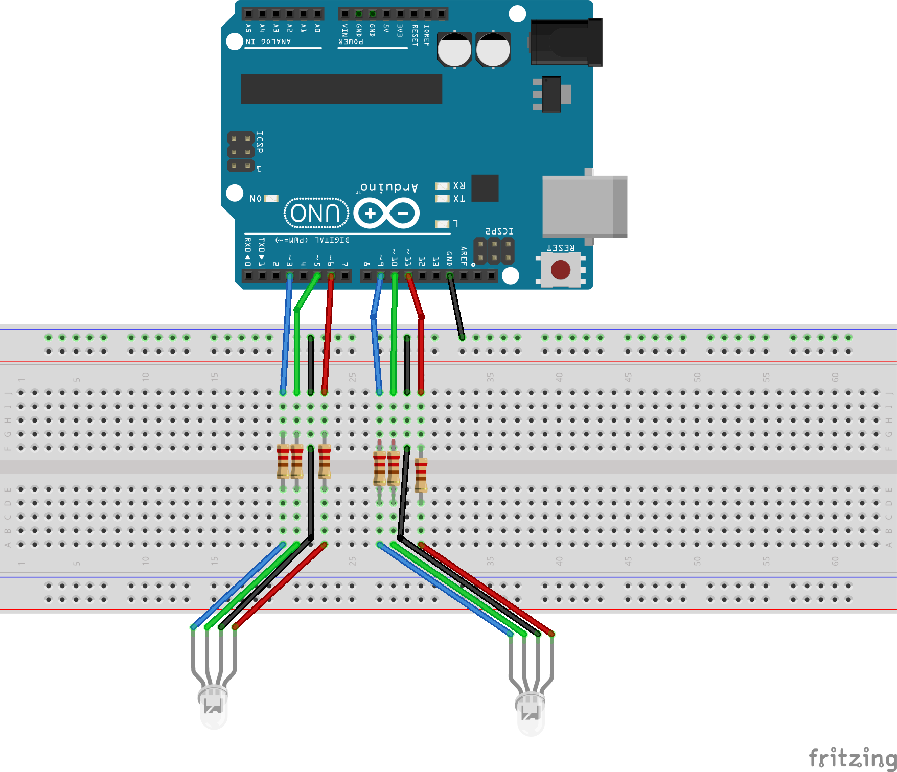
PHASE I : THE ARDUINO SIDEWorking our way up, we start with the Arduino. Since I was using different colours, I used the two RGB LEDs that came in my starter kit. You could add more, or even take it a step up and sync it to those light strips once you find a way to communicate to them but I'll use what I have. Using the 6 PWM pins on the Arduino, I wired things up as in the diagram section. I did use the male to female connectors so that I could put the lights wherever I wanted them. These were loose so some tape was required. The lights were also a bit harsh so I diffused them with some white tissue paper.
It just happened that my laptop stand (yes, it's made from LEGO) had a breadboard-sized gap underneath it but you'll have to integrate your lighting some other way if not. Perhaps off to the side of your computer or behind the monitor
With this now, I just experimented with colours until they matched up to the elements. A light, bright blue for the ice element, a deeper one for the water element and a warmish green for the wind element. Then I wrote the if loops for if the trigger was detected, then to turn on the light. That trigger part will come a bit later down.
PHASE II: THE BRIDGINGAll the complicated fancy screen detection stuff is handled over on the Python side, as Arduino really isn't equipped for that. We need a way to communicate from Python to Arduino, and that would be handled by the serial port. If you've ever done a project where you enter a command into the serial monitor of the Arduino, it's that exact same concept. Python has a module that allows it to communicate to the serial port, and then our Arduino reads that, and sets our lights off.
Shoutout to the most excellent Paul McWhorter for the Python + Arduino tutorials where I learned this from and you should probably take a gander at it yourself here if you want to understand better
In short (and in very rough terms), on the Python side:
1.) We install the PySerial module in the terminal
-pip install pyserial
2.) Create an object that affixes our command(a string) it to the respective serial port and baud rate.
arduinoData = serial.Serial('com3',115200)
3.) Set a command (mine was SS) and attach a certain character on to it
cmd = "SS" + '\r'
4.)Send the command to the Serial
arduinoData.write(cmd.encode())
Now on the Arduino side, we just need to read the serial monitor. It continually reads it until the character '\r'. This is the character for the carriage return, which sets the string after it on a new line. Without it, the strings we send from python would just in one very long line. So reading until this tells Arduino to read everything before a new line is started. This is done through
mode=Serial.readStringUntil('\r');
Now, we can trigger something off like this
if (mode=="SS"){
analogWrite(rPin,0);
analogWrite(gPin,0);
analogWrite(bPin,70);
analogWrite(gPin2,0);
analogWrite(bPin2,70);
}
With that sorted out, up next is the part where we decipher is the ult indicator is up or not.
PHASE III : OpenCV and PythonPython has a lot of versatility that Arduino doesn't. Specifically, the vast OpenCV library most known for things like face detection. OpenCV also gives us access to template matching, to match our ult icon with the current screen. Aside from that, we need to make use of the win32api to allow rapid screenshots that are stitched together to form the live video feed of our screen. These tutorials were an amazing starting point for these complicated things (well, for me) I just took what I needed though, since my objectives were different.
I'll run over what I took from it in words here. This part was beyond my complete understanding and I just had to blindly follow along the tutorials in some parts so pardon any mistakes.
We use the cv.matchTemplate() function to find a needle image (the ult indicator) in a haystack(the live screen).
The function returns four values, of just one we need. This is the confidence value of the best match on a scale of 0-1 (max_val). The location values are the coordinates of the top left corner of the best/worst matches. By setting a threshold, we can detect if our desired image is present or not.
Here's something you could try for yourself to see it in action. Use a screenshot of your screen in whichever application as the haystack and then crop a bit that you want to be detected as the needle image. Just replace the names of haystack.png and needle.png with your picture names. These images need to be moved to your project file before the program can read it though.
This program draws a rectangle over the detected image so we can get an idea of how well the matching works.
import cv2 as cv
# reads the images
haystack_img = cv.imread('haystack.png',cv.IMREAD_UNCHANGED)
needle_img = cv.imread('needle.png',cv.IMREAD_UNCHANGED)
# assigns the results to variables
result = cv.matchTemplate(haystack_img,needle_img, cv.TM_CCOEFF_NORMED)
min_val, max_val, min_loc, max_loc = cv.minMaxLoc(result)
threshold = 0.9
if max_val >= threshold:
 print('Found needle')
 print(f'Best match top left position: {max_loc}')
 print(f'Best match confidence: {max_val}')
 # gets dimensions of our needle image
 needle_w = needle_img.shape[1]
 needle_h = needle_img.shape[0]
 # dimensions of rectangle
 top_left = max_loc
 bottom_right = (top_left[0] + needle_w, top_left[1] + needle_h )
 # draws rectangle over where the image is detected
 cv.rectangle(haystack_img, top_left, bottom_right,
 color=(0,255,0), thickness=2, lineType=cv.LINE_4)
 # displays result until a key is pressed
 cv.imshow('Result', haystack_img)
 cv.waitKey()
else:
 print('Needle not found')
For my haystack and needle, I used the following images
And got this as my result
This is the basis of the object detection. From here, we just check if the confidence is above our threshold and if yes, we send the Arduino the string through the serial port, it reads it and activates whatever we set it to do. Before that though, we need to figure out a way to feed continuous screenshots to the detection part.
For this, we use the win32api. This part of the project was defined as a class in another file to keep things tidy. We just import it into our main file after. On initialization, you enter your window size, or the whole monitor if you wanted to do that. Then, a screenshot is taken of the defined area, some processing happens, and then data is cleared to free up system resources. Ultimately it returns a screenshot of your desired area and the detection loop checks it through, rinse and repeat.
The larger your screen area is, the more processing has the be done and the slower your program runs and may even affect your application performance. For my case, I set my area to 80x80 pixels since it's a static area that the ult indicator lies on. I found this by cropping the image in windows and finding how big the cropped window was. I entered this in the init part of the code. You could also enter the name of your application window for OpenCV to stay focused on it but it wouldn't work for my game, so I left it as None and whatever window was on top was captured.
class WindowCapture:
 w = 0
 h = 0
 hwnd = None
 def __init__(self,window_name):
 self.hwnd = win32gui.FindWindow(None, window_name)
 if window_name is None:
 self.hwnd = win32gui.GetDesktopWindow()
 if not self.hwnd:
 raise Exception(f'Window not found:{window_name}')
 # Size of the section of the screen that is being captured
 # Put monitor resolution for whole screen
 self.h = 80
 self.w = 80
Do note that your needle image has to be inside here and since those margins are very fine, it's best to leave some space for error. My needle images were 75x75 so even if I cropped the corners a little off, it would still be found somewhere in there.
We also need to set the top left of the corner of our desired section in the code lower down.
#Coordinates of the upper left corner of the section captured
# Put 0,0
cDC.BitBlt((0,0),(self.w, self.h) , dcObj, (1779,932), win32con.SRCCOPY)
These coordinates were handily provided by the cv.matchTemplate() function.
Now, a screenshot of this area of the screen is returned from calling the function. This is plugged into our main file for template matching to compare our needle image against.
while(True):
 screenshot= wincap.get_screenshot()
 threshold = 0.9
 SSneedle_img = cv.imread('SakuraSwirl.png',cv.IMREAD_UNCHANGED)
 result = cv.matchTemplate(screenshot,SSneedle_img, cv.TM_CCOEFF_NORMED)
 min_val, SSmax_val, min_loc, max_loc = cv.minMaxLoc(result)
if (RCmax_val>=threshold):
 cmd = "SS" + '\r'
else:
 cmd = "No ult" + '\r'
While the on the Arduino side of things.
mode=Serial.readStringUntil('\r');
if(mode== "SS"){
analogWrite(rPin,10);
analogWrite(gPin,20);
analogWrite(bPin,100);
analogWrite(rPin2,10);
analogWrite(gPin2,20);
analogWrite(bPin2,100);
}
else{
analogWrite(rPin,0);
analogWrite(gPin,0);
analogWrite(bPin,0);
analogWrite(rPin2,0);
analogWrite(gPin2,0);
analogWrite(bPin2,0);
}
Don't mind that cmd and mode are two different variable names. You could set them as the same, but it works all the same. They're in two different environments so it's not a problem.
This was the basis of one ult, but since I have four different ones to keep track of, I just used the same logic and made multiple detection blocks with the same haystack image, and different needle images. Note that if you want to do something similar, you'd have to use elif loops after the first if loop on the Arduino side because mine kept triggering off multiple lights.
ALL TOGETHER NOWWith all the files, modules, pictures and everything in place now, it's ready to be used. Here's a clip of me in combat with a very furious rooster thing. The blue and light blue were a bit hard to tell apart in the video, and the lights looked like blobs on camera rather than a nice under glow but it works. Vertical recording was the only way to get everything in frame unfortunately.
I also gave it a go using the other characters to showcase the other colours.
You can see that it skips a little bit in some areas. That's because of the translucence of the indicator paired with one of the darkest areas in the game.
Since you use the ults in this game as soon as they're up, you don't really see the lights up much when you're playing. I tried my hand at something else too, which was syncing the ult with a character's animation and it came out decently. I used the keyboard module for this. Took a LOT of testing and fine tuning though so I don't think it's something I want to do for every character.
QUICK STARTTo do this for yourself, here are the steps. This is for an instance where we're only tracking one area that's static. You could do multiple detections over a large area too, but the openCV tutorials above would be your best bet for that. We'll start with the screen detection.
STEP 1: Getting all your images and files setup
• Make a folder to store all your project files.
• Obtain a screenshot of the application you want to use, and crop the smaller bit as a separate image that you want to detect. Make sure to note the measurements of this image since it'll be the smaller window that's being focused on later on.
• Download or copy paste the provided python files in the code section (mainDetection, windowCapture, templateMatching)
• Upload all of these these to your project file
STEP 2: Setting up prerequisites
• Open your project file in your code editor (I used VSCode)
• Setup a virtual environment (this allows us to install libraries and packages to just this environment, which might cause issues if we installed globally)
For this, go open the terminal in your project file and enter
python -m venv Tutorial
where tutorial is the name of the virtual environment. Then activate it with
Tutorial/Scripts/activate
You'll know it's activated when you see the name pop up in green brackets in the terminal like so
• Install all the modules being used. These are openCV, win32api, PySerial and the keyboard module. Enter the following lines into the terminal
pip install opencv-python
pip install pywin32
pip install pyserial
pip install keyboard
STEP 3: Modifying the windowCapture to your use
• First use the templateMatching file and edit the name of the haystack and needle images to yours. This needle image won't be the final one, this step is more to determine the area that you'll be cropping.
You could actually use that needle image it as the final one, but since I cropped four different images on one spot, they wouldn't have the same center. Unless I drew lines over the icon and then cropped it but that was too much of a hassle.
The program should return the coordinates of the upper right corner of the detected area. Close it and now, go into the windowCapture file and change the self.h and self.w size to your initial needle image dimensions. You can also enter the application window name here too.
class WindowCapture:
 # leave h,w as 0 here
 # enter window name exactly as string for hwnd if known
 w = 0
 h = 0
 hwnd = None
 def __init__(self,window_name):
 # put same window name as second parameter if using
 self.hwnd = win32gui.FindWindow(None, window_name)
 if window_name is None:
     self.hwnd = win32gui.GetDesktopWindow()
 if not self.hwnd:
     raise Exception(f'Window not found:{window_name}')
 # Size of the section of the screen that is being captured
 # Put monitor resolution for whole screen
 self.h = 80
 self.w = 80
Then later down, in the get_screenshot() function, you'll enter the upper left coordinates in this line
cDC.BitBlt((0,0),(self.w, self.h) , dcObj, (xcord,ycord), win32con.SRCCOPY)
Lastly you have the option of trimming a few further pixels off the needle image to give it wiggle room if you have multiple. Like how I went from 80x80 to 75x75 in the explanation above. If it's just one, it should work perfectly though.
STEP 4: Modifying the mainDetection file to your use
You'll need to change the Arduino port that you use as well as the baud rate at the top of the file. Then, you can delete all the excess detection and if blocks since I needed four of them.
Adjust the command/s to your liking and that should be about it. I used the shortened version of the ultimate move names as mine e.g. Raincutter was RC.
There's also the threshold variable that you can play around with. I'd recommend trying multiple haystack images in the templateDetection file to get an idea of what your threshold would be. Some games with a day-night cycle or transparent indicator icons would need a lower one. For example, since the ult indicators are translucent when not fully charged, sometimes grassy areas can give false positives for a split second for the green ult icon.
There's a fps counter in this code that prints it to the terminal, but you can comment that out after some trial runs. At this very small size, I was getting 140-160 fps but bigger windows would take up more resources again, as well as your computer's capabilities. This completes all the python-side things. The end of the program sends a string to the Arduino that we'll proceed to read.
STEP 5 : Arduino reading and effects
This line does most of the magic for us
mode=Serial.readStringUntil('\r');
Hook up the lights (or output device of your choice) and write the if loops to detect the same command string that your python file is sending over, then to perform the action.
STEP 6: Final touches and troubleshooting
The serial port can't be used by two sources at once, so first you'll upload your file to the arduino, then you'll run the mainDetection file and leave it in the background while you run your game. The code editor should be run as an administrator to ensure this works. When uploading and running the program, you'll want it to give it a few seconds in between for the serial port not to bring back any unavailable errors.
Hopefully it works, but I've had trouble with this before and the main culprits are the window capture size and the threshold value. I initially used a much bigger window capture area but then the game's environment showed up which varies from snow to forests to deserts, and this threw off the detection a lot. That's why I opted for such zoomed in needle images. You can also print the confidence value (max_val), and see where things are going wrong if they are.
That should wrap it up; your very own gimmicky lights.


Comments
Please log in or sign up to comment.