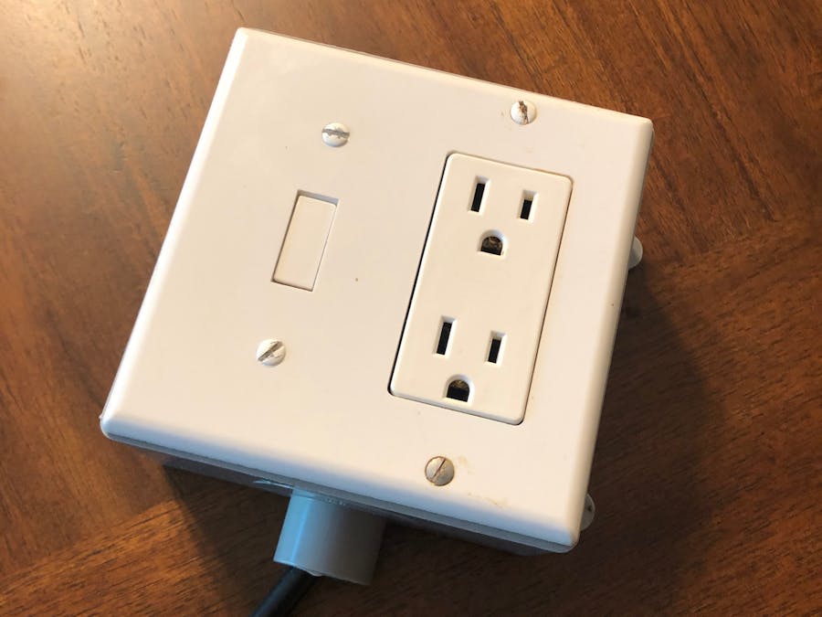
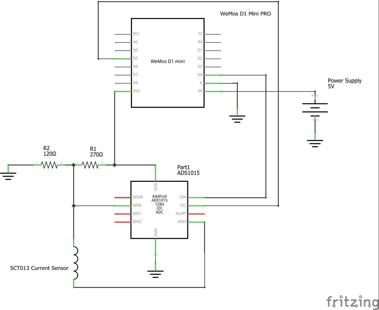
This project measures AC current of whatever devices are plugged into it. Its MCU is a Wemos D1 Mini Pro. It measures the offset voltage and the current voltage by a ADS1015 analog-to-digital converter. The actual current measurement is done by a YHDC SCT013 30A/1V current sensor. Powering it is a 5v, 1A power supply.
It operates as follows: The primary load AC line goes through the SCT013 current sensor to the outlet. When a device is plugged into the AC outlet, the SCT013 detects the current flowing through the wire which goes through the center of the sensor. It and detects the secondary voltage that is inducted from the current flowing. It outputs a linear voltage between 0-1 V DC, 0v being 0A, 1v being 30A.
Lets say you have 1V AC current. The actually swings between 1v & -1v AC. Its more work to work with negative numbers so I overcome this by putting a offset voltage on the line to the SCT013. Using a voltage divider, I take 3.3V down to about 1.015 V DC and use this for our offset voltage. This allows all numbers to remain positive. So for example if you had 30amps AC, that would output 0.015 - 2.015 Volts DC because its starting with 1.015 volts and the AC measurement voltage swings around that.
For accuracy, The actual offset voltage is measured initially on power up by the ADS1015 so It knows exactly how many volts to deduct from the SCT013 output. It should have nothing plugged into the outlets on power up so it gets a accurate offset measurement. It the samples the voltage for a 1/2 second (as that should catch about 30 cycles of the AC waveform) and records the max value. It then deducts the offset voltage from that to leave us with the actual voltage output from the SCT013. We then calculate the current by multiplying by 30 ( because we know 1v == 30A). For calculating watts, it just needs the AC line voltage which defaults
This uses the peak wave method for measuring the AC current so it is not a true RMS reading of the current. It still is pretty accurate with this method.
It displays all the information on the Blynk app. It shows: current, current kWh, cumulative kWh, Wifi RSSI, offset reading, measured reading, and adjusted value. User controls are specifying AC voltage, reset offset voltage, reset cumulative kWh, & restart chip. It uses the EEPROM to stores the running (cumulative) kWh every hour encase of power loss. I also included over the air code so that it can be programmed/updated without having to open up the case & manually plug into the USB.
When compared to AC current measured using a Kill-a-Watt meter, it is the same with a deviation I've noticed of about +/- 0.1 amps
As always, be safe with electricity. If you don't know how to properly work with and wire AC circuits, don't try this.
*If anyone finds anything wrong with my logic or methods please let me know.*


Comments
Please log in or sign up to comment.