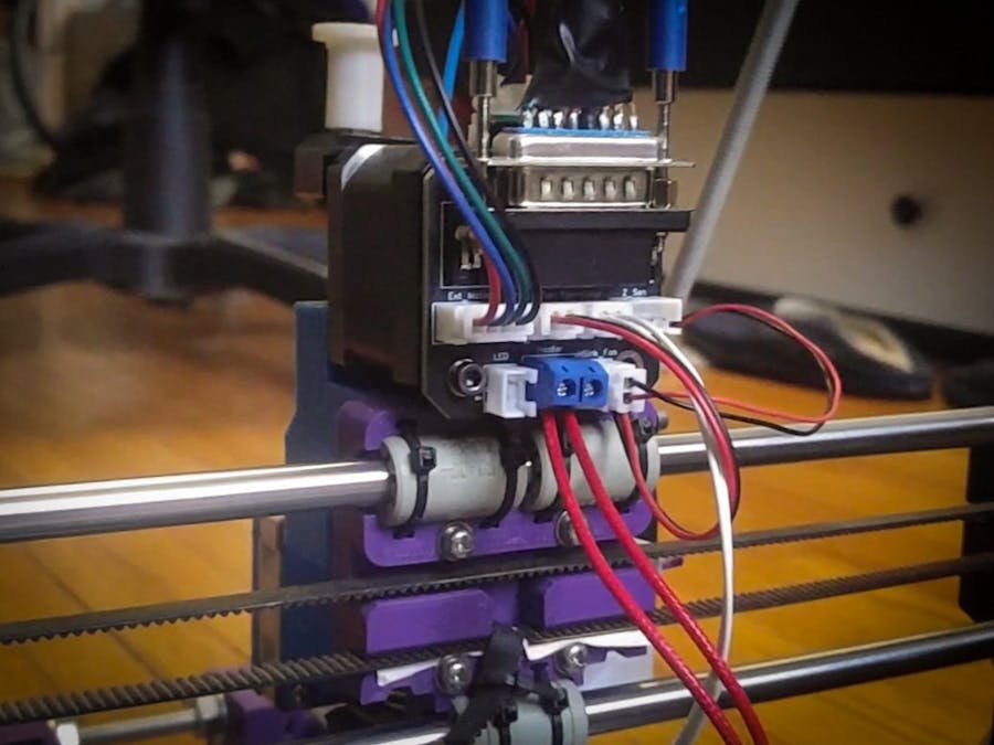
Thermistor kicked the can? Good luck getting it out of the drag chain, all for one part. Serviceability has a tendency of becoming secondary, but with this inexpensive hot swap board, there's no need to dismantle the entire cable assembly.
This hot swap board also opens the door to multiple tool heads; albeit, it likely won't be not automatic. I aim to reuse as many existing parts as possible.
Bill of MaterialsParts are reused when applicable. Wires for each component can be used for the custom cable. This JST kit has been very useful.
- Quick Swap PCB [x2]
- DB15 Right Angle Female Connector [x2]
- DB15 Straight Male Connector [x2]
- JST-XH-04 Male Connector [x2]
- JST-XH-03 Male Connector [x2]
- JST-XH-02 Male Connector [x8]
- 2 Pin Screw Terminal [x2]
- Braided Sheathing 12mm
- 1206 SMT Resistor
- Existing Wires from Components
- Spare Wires
- 35mm M3 Screws
- Printed Brackets
- DB15 Housing (Or printable housing; STL included here)
- Soldering Iron
- Wire Strippers
- JST Crimp Tool
- 3D Printer
Source Files
I've included a link to my online EDA, which can be modified freely.
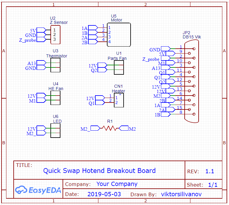
DevelopmentThe PCB is effectively a breakout board, with no ICs, logic, or microcontrollers. It was most important to (1) use a main connector with enough pins, (2) ensure each pin on every connector was capable of carrying the required current, and (3) comply with JLC PCB's manufacturing criteria for the most economic option.
The footprint is the same as the rear of a NEMA 17 motor, and has mounting holes aligned with the screws that keep the motor together.
I left a spare port for miscellaneous add-ons such as LEDs..
Total: 17 pins across 7 connectors
Some components share pins, allowing me to reduce the number of pins required for the main connector down to 13 pins.
The DB15 connector was selected because:
- Maximum current per pin is 5A, which is sufficient to drive the heater cartridge. A 40W heater at 12V draws 3.33A.
- No crimp tools/jaws required, as pins are directly soldered to.
- Built in strain relief via screw posts.
I referenced the RAMPS schematic to understand how components were driven. Most 8 bit AVR boards are a redressed RAMPS. 32 bit boards may drive their components differently.
I spread 12V across multiple pins because I don't trust that my Chinese DB15s are actually rated for 5A.
The LED is tied to 12V and requires a low side switch to work.
PCB designTo keep the PCB cost down, I had to use 1oz copper fill, which means I had to be cognizant of my trace width so it could deliver enough current. The trace width calculator is a great tool.
The top copper plane is power instead of typical ground. I couldn't route a thick enough trace otherwise.
The bottom copper plane was turned into M1, which is the drain of the transistor that will ground the return path.
Signal traces were kept thin, while power traces were wide enough to carry the required current.
I included 2 printable brackets. The first bracket is a spacer between the motor and the board, while the second is for the board at the control side.
Note: Use M3 screws than those securing the motor.
I also designed a 2 piece housing for the DB15 connectors.
Cable assembly:
Cable connections are symmetrical.
The cable was heavier than I expected, but more rigid. It did not flop over.
Board assembly:
Installation:
On the control side, I made some additional cables between the hot swap board and the main board.
New extruder assembly in action:
*Edit 5/20/2018*
I made a version for BLtouch users, but it is untested and I cannot guarantee it will work. This is meant to serve as a starting point for further development.
The BLtouch PCB can be found with the rest of my EasyEDA source files.


Comments
Please log in or sign up to comment.