Robotics have being a huge field of interested for our team, and this is the first time we have the chance to use a set with an independent micro-controller thanks to the Dynamixel shield.
The project although nothing new or original is intended as a user guide to new robotics enthusiasts with access to the Bioloid kit, and as a proof that things can be achieve even with basic robotics sets.
The design can be extended to work as a social distancing for clerks on banks or federal offices to receive documents without direct physical contact and preserving the required distance.
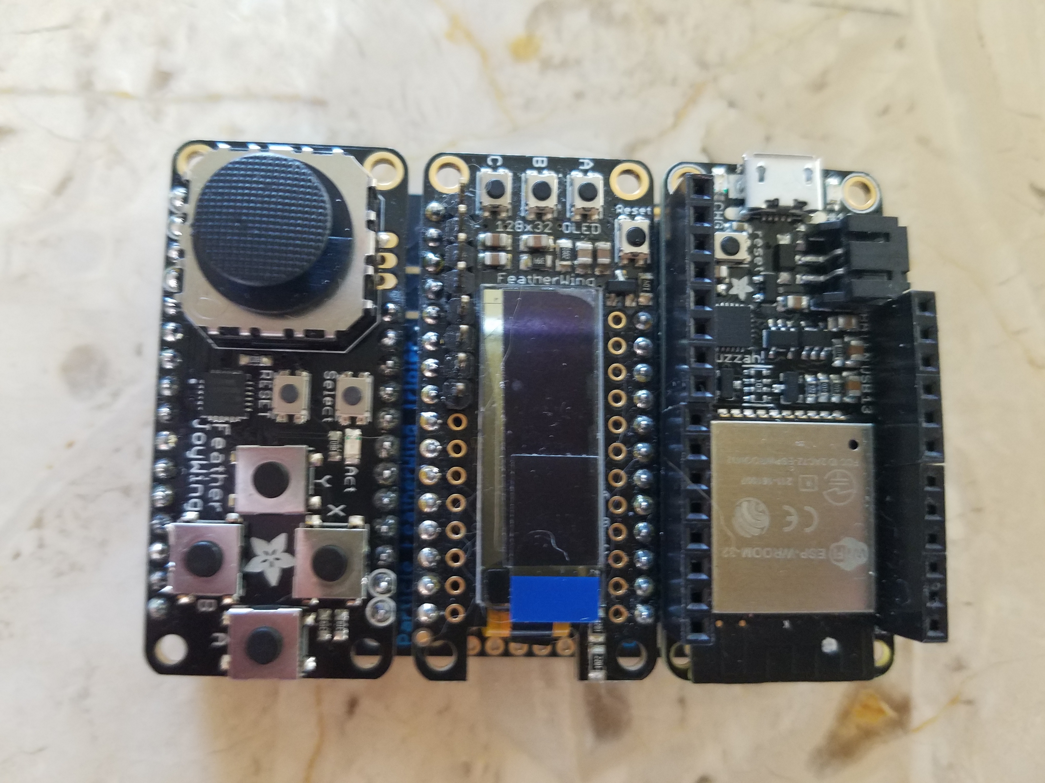
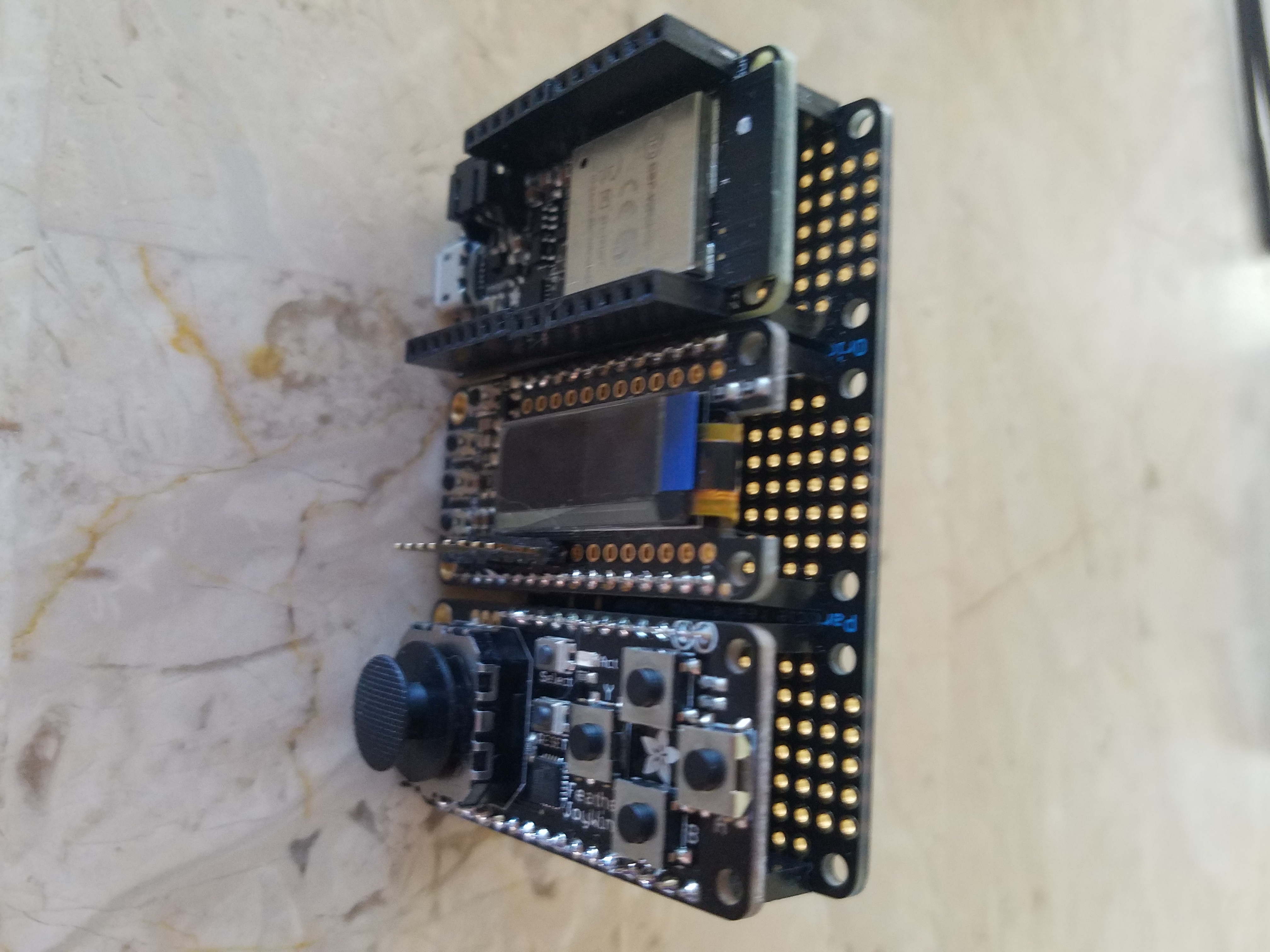
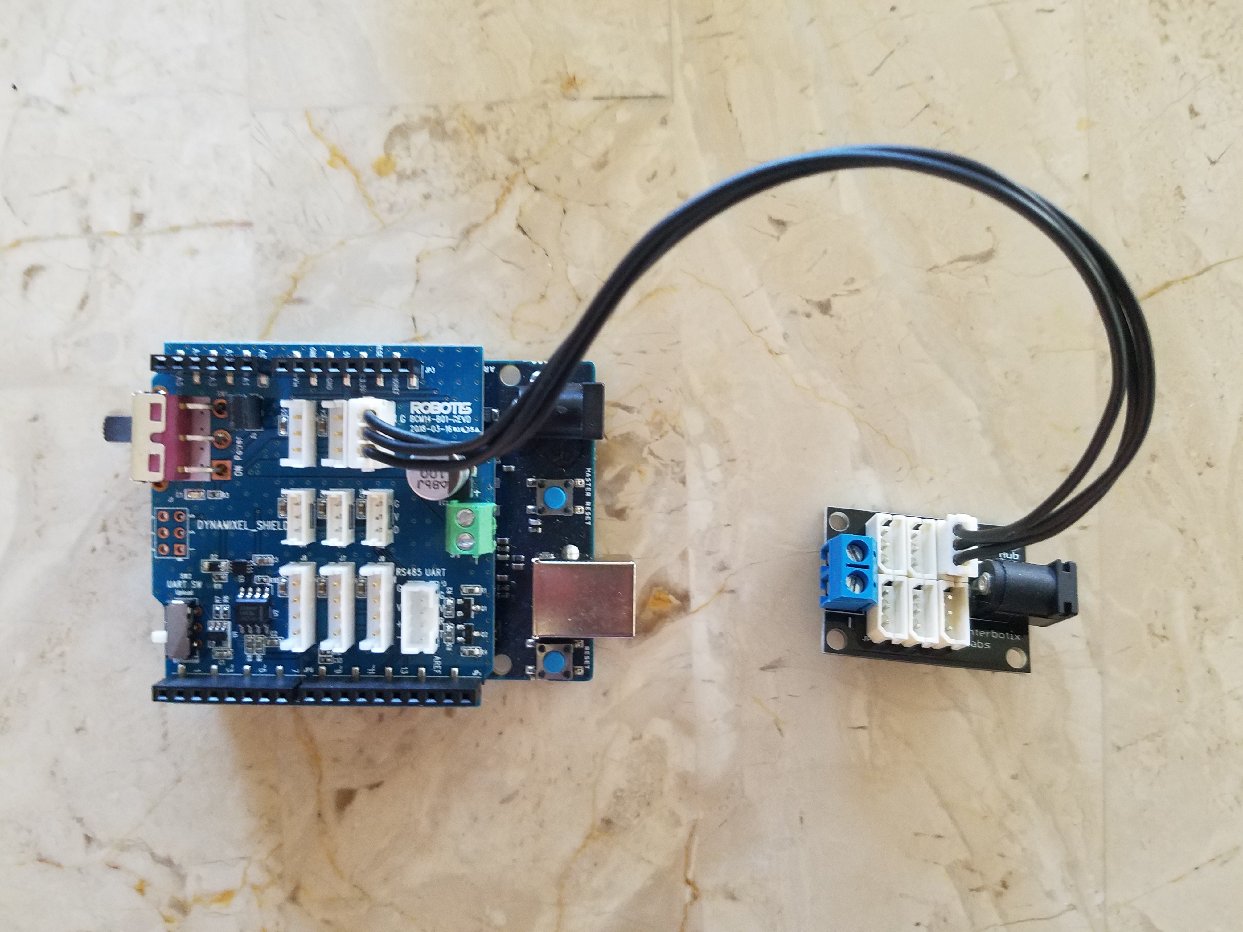
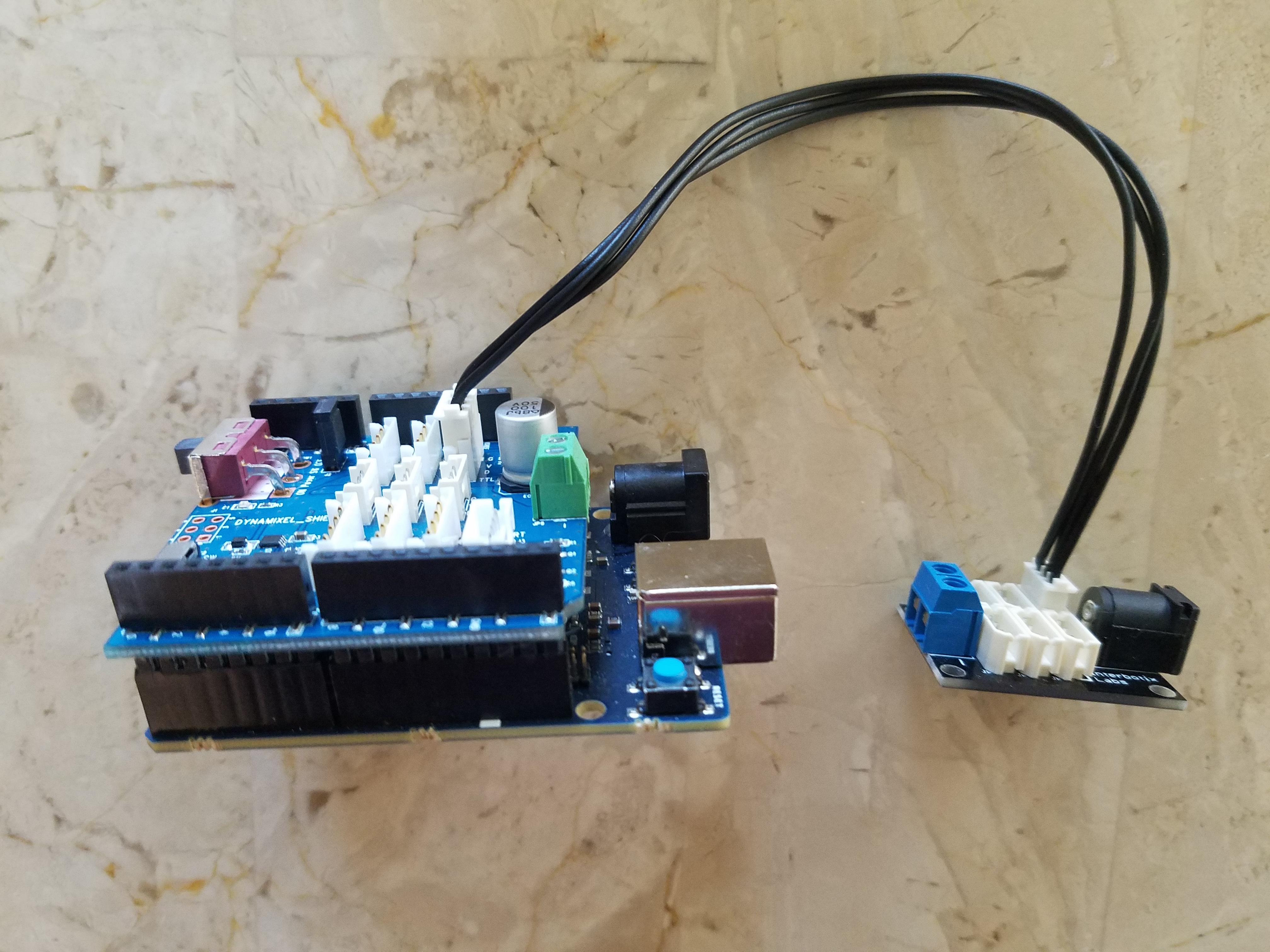
MaterialsWe use the Robotis Dynamixel Shield and libraries to control the AX series servos from Dynamixel, connected to an Arduino 101 board. The control interface is done using an Adafruit Feather HUZZA32 and an Adafruit Joy Featherwing. We use a total of 4 dynamixel servos, three AX-18A and one AX-12A, and the Bioloid frame parts to build the arm.
Other components are shown in the below snapshots.
We use the startup guide from Robotis to install the shield, and you can access the latest API library here.
The library installation includes samples to manage the module. We found that using the module on an Arduino Genuino is tricky since the DEBUG serial port uses a software port and we couldn't make it work. Using an arduino 101 fixed the issue since it has two serial ports to handle the debug data and the communication with the shield.
We also found that some old Dynamixel servos requires of protocol 1.0 instead of 2.0, like the AX-12A and AX-18A we have. Make sure to you run the scan_dynamixel sample with the protocol changes and you will find servo id's and communication speed, these data is needed to establish a link with the connected servos. You could also find the software tools in the Robotis site useful, make sure you select the version that corresponds to your hardware.
The shield has a switch that allows the programming of the micro-controller by releasing the UART port during upload of the program, changing the switch to Dynamixel will send the commands to the servo connected. See image here.
Finally, the module have a power connector to provide power to the hardware devices, or you can use a power HUB to provide such power. Using the power from the Arduino board is not recommended and does not provide the 9 V minimum requirement that some servos need.
The programming of the module is initialize by instantiating an object of the Dynamixel library. The parameters indicates the UART serial port to use communicating with the shield and the DIR PIN.
Dynamixel2Arduino dxl(DXL_SERIAL, DXL_DIR_PIN);Once the object is instantiated, begin communication using the baudrate found on the scan process for you Dynamixel hardware. Indicate the protocol to be used, currently 1.0 and 2.0 are supported, then start the hardware by using the ping function with the servo ID. For each servo ID turn off the torque property since we need to set the direct positioning property of the servo, once done turn the torque on again. Repeat this for each servo connected.
// This has to match with DYNAMIXEL baudrate.
  dxl.begin(1000000);
  // Set Port Protocol Version. This has to match with DYNAMIXEL protocol version.
  dxl.setPortProtocolVersion(DXL_PROTOCOL_VERSION);
  // Get DYNAMIXEL information
  dxl.ping(HAND_ID);
  dxl.ping(WRIST_ID);
  dxl.ping(ELBOW_ID);
  dxl.ping(SHOULDER_ID);

  dxl.torqueOff(HAND_ID);
  dxl.setOperatingMode(HAND_ID, OP_POSITION);
  dxl.torqueOn(HAND_ID);
When data is received and one of the servos need to be position use
dxl.setGoalPosition(SHOULDER_ID, cmdCoordX);It did take us some time to get the different definitions of BLE support on an Arduino 101 and the ESP32. The Arduino 101 treats the devices that consume BLE data as central device and the ones that send the data as peripherals. The Adafruit HUZZAH32 ESP32 device defines a central as a client and the peripherals as servers.
In our project we create an UART service thru the ESP32 with the following UUIDs
#define SERVICE_UUID           "8907022f-2a69-4dc4-9b98-85b1356ef422" // UART service UUID
#define CHARACTERISTIC_UUID_RX "42f1162a-4dea-4901-97ca-9cca75a1e8a3"
#define CHARACTERISTIC_UUID_TX "581108e2-6a9a-40d3-9d5f-db6f7529aa6a"
The first UUID will be use to create the service, and the other two define characteristics of the service.
// Create the BLE Device
  BLEDevice::init("ROBOTTE Service");

  // Create the BLE Server
  pServer = BLEDevice::createServer();
Notice that the inti function defines the service name that will be published to the listening devices and the createServer defines the device as a server.
// Create the BLE Service
  BLEService *pService = pServer->createService(SERVICE_UUID);

  // Create a BLE Characteristic
  pTxCharacteristic = pService->createCharacteristic(
                    CHARACTERISTIC_UUID_TX,
                    BLECharacteristic::PROPERTY_NOTIFY
                  );

  pTxCharacteristic->addDescriptor(new BLE2902());

  BLECharacteristic * pRxCharacteristic = pService->createCharacteristic(
                       CHARACTERISTIC_UUID_RX,
                      BLECharacteristic::PROPERTY_WRITE
                    );
Then the service is created, together with the characteristics UUID and types. Notice that the TX characteristic is defined as a NOTIFY property which will send notification once new data is available to transmit.
The service and server is started by executing
// Start the service
  pService->start();

  // Start advertising
  pServer->getAdvertising()->start();
We then submit new data thru
if (deviceConnected && strlen(msg) > 0) {
        pTxCharacteristic->setValue(msg);
        pTxCharacteristic->notify();
        delay(10); // bluetooth stack will go into congestion, if too many packets are sent
  }
Notice the notify() function which sends a wake up message to the listening devices so they can extract the new information and processed it.
We use the nRF Connect app from Nordic Semiconductor to test the service and confirm that the data and the service are transmitting correctly. You can see the test on the video above.
On the client device we connect to a service by starting the BLE and scanning the available peripherals. Check for a matching peripheral with our needed device, in this case ROBOTTE Service.
BLE.begin();
  // start scanning for peripherals
  BLE.scan();

  while (notFound)
  {
    BLEDevice peripheral = BLE.available();
    if (peripheral) {
      // see if peripheral is our UART service
      if (peripheral.localName() == "ROBOTTE Service") {
Connect to the peripheral, and register to the service to receive messages.
// connect to the peripheral
        if (!peripheral.connect()) {
          Serial.println("Failed to connect!");
          return false;
        }


        // retrieve the LED characteristic
        BLECharacteristic notifyCharacteristic = peripheral.characteristic("581108e2-6a9a-40d3-9d5f-db6f7529aa6a");
Connect to the Notify characteristic using the UUID set on the server device.
Confirm that the connected service and characteristic has a notify property and subscribe to the events. Register a callback function to the characteristic which will be call on every new data sent.
if (notifyCharacteristic.canNotify())
          {
            notifyCharacteristic.subscribe();
            notifyCharacteristic.setEventHandler(BLEValueUpdated,UpdateValue);
            joystickPeripheral = peripheral;
          }
The callback function on our project is defined as
void UpdateValue(BLEDevice bledev, BLECharacteristic characteristic)
{
  char *data;
  data = (char *)characteristic.value();
  Serial.println(data);
  if (strstr(data,"START"))
  {
    StopFlag = true;
    characteristic.unsubscribe();
  }
Note that the function receives objects to the BLE device and the subscribe characteristic. The function then retrieves the value sent in the characteristic and then it scans for commands and splits the data. Notice that the START command stops and unsubscribes to the service, allowing the BLE server to stop notifications to this client.
The defined commands are:
#define CMD_OPEN_HAND   1
#define CMD_CLOSE_HAND  2
#define CMD_WRIST_HAND  4
#define CMD_ELBOW_SHOULDER 8
Each command is used as in the next sample:
if (strstr(data,"cmd:B"))
  {
    if (lastCmdData != CMD_OPEN_HAND || lastCmdData != CMD_CLOSE_HAND)
    {
      lastCmdData = cmdData;
    }
    cmdData = CMD_CLOSE_HAND;
  }
Notice we check if the last receive command is the same as the currently received, this helps to avoid multiple commands received. The program expects one unique command per data cycle.
Then the loop executes the corresponding command with the received data, as we will see on the Robot Arm section.
Joystick InterfaceThe Adafruit Joy Featherwing setup guide from Adafruit is simple and straight forward, you can access it here.
In our program we instantiate an object to the class Adafruit_seesaw
Adafruit_seesaw ss;A mask is defined in order to process the buttons in the shield
uint32_t button_mask = (1 << BUTTON_RIGHT) | (1 << BUTTON_DOWN) |
                (1 << BUTTON_LEFT) | (1 << BUTTON_UP) | (1 << BUTTON_START);
Then initialize the pins using the mask and activate the event on pull up. Turn on the GPIO interrupts and the pin to use as interrupt notify.
ss.pinModeBulk(button_mask, INPUT_PULLUP);
  ss.setGPIOInterrupts(button_mask, 1);
  pinMode(IRQ_PIN, INPUT);
Check if a button has being pressed
if(!digitalRead(IRQ_PIN)){
    uint32_t buttons = ss.digitalReadBulk(button_mask);
    if (! (buttons & (1 << BUTTON_DOWN))) {
      display.println("B");
      sprintf(msg,"cmd:B          ");
    }
Read all the buttons status with the digitalReadBulk function and start verifying which button was pressed by masking out the result.
The joystick data is read as an analog input
int y = ss.analogRead(2);
  int x = ss.analogRead(3);
Format the data and send it thru the BLE service.
Robot ArmThe arm is build using the Bioloid framework and Dynamixel servos AX-18A and AX-12A.
The arm body design was taken from the robot guide for the Bioloid set. The head of the hand was a self design to allow the wrist turn around with the hand centered on the fingers. You can see a 3D view at the end of the video above.
Robot TeWe us the Adafruit FeatherWing Tripler to connect the ESP32, joystick and display to control the arm. This interface is easy to put together and to grab with your hand.
The above video shows a demo of the interface.
The arm servos are connected to a power HUB using a plug in power delivering 9V of current. The arduino and ESP32 are connected to LIPO batteries. The power consumption on these devices is minimum.
We notice that using this configuration in some extend created hiccup transmission issues.
Minimal InterfaceWe finally tried a minimal interface by attaching the joystick directly into the ESP32 board. This configuration is smaller and user much less power than the one with the display attached.
We also notice a more stable transmission than the one with display.
A demo of the interface is shown in the above video.
Future WorkImprove the latency by using binary commands instead of string. Improve the movement smoothness when positioning servos.
THANKS FOR READING. :)


_baVEVgguW1.jpg?auto=compress%2Cformat&w=48&h=48&fit=fill&bg=ffffff)


Comments
Please log in or sign up to comment.