Robotics is currently a rapidly developing area, every year more and more processes are automated and human work is minimized. But in order to develop this direction it is necessary to train young professionals who could quickly join the study of the basics of this area, without doing routine and unnecessary work.
To learn the basics of robotics, students should study directly with robots and apply their knowledge in practice. At the moment, the most popular platforms for training are: ATmega328P microcontroller and Raspberry Pi 3 microcomputer.
The Raspberry Pi 3 has much more features compared to the Arduino, so its learning to put in priority. By itself, the micro-computer Raspberry Pi 3 is a small charge (Fig.1) which is a full-fledged computer. But in order to fully use it, you need to expand its functionality and make its use convenient and versatile, you need to solve the following tasks:
1. Provide independent power supply to the power part of the robot (12V), which is responsible for the stable operation of electric motors.
2. Provide power to the microcomputer Raspberry Pi 3 (5V, 2A), here should pay special attention to the stabilization of the current.
3. Expanding the capabilities of Raspberry Pi 3 through the use of ADC
4. Provide fast and reliable connection of individual parts of the robot, through the use of connectors.
All these tasks are usually done through the use of separate modules, which entails an increase in the mass-dimensional characteristics of the robot and its cost. Therefore, it was decided to develop a module that would perform all the above tasks, was compact and versatile.
In any robot to perform its tasks it is necessary to provide the necessary levels of voltages and currents.
From the initial conditions for the calculation it should be assumed that the input voltage, but during operation, the voltage from the batteries will fall, but this should not affect the stability of the work. As the electric motors the majority of robots are designed for is necessary to acspect stable power to the electric motors through the use of a pulse controlled DC-DC Converter LM2596 in the instructions for use[1], which provides proizvodil you can find the concept of inclusion (Fig.2) and formula (1) to calculate the output voltage. Substituting the voltage values in the formula (1), you can Express the resistance of the resistors and choose the nearest at par. All other elements are selected according to the manufacturer's recommendations.
The next point in the development is the task of providing the Raspberry Pi 3 microcomputer with a stable voltage of 5V and a current of 2A, this is necessary to ensure a stable and fast operation of the operating system, since experiments show that reducing the current to 1A entails a decrease in performance, and reducing the current to 0.5 A entails switching off the microcomputer.
To perform this task, the best solution is to use a step-down converter MP1593, the schematic diagram is shown in Fig.3 in the instructions for use[2], a table is given where the desired output voltage parameters and the ratings of the electrical components that must be applied.
Since there is no built-in ADC on the board of the Raspberry Pi 3, it is necessary to use an external 8-bit pcf8591 ADC, the instructions for use[3] show the simplest scheme for connecting this ADC via the I2C interface.
To quickly connect additional devices to this extension, it is better to use different types of connectors, for example, in order to output the GPIO ports of the Raspberry Pi 3, it is better to use the connectors of the type PLS, to connect the module to the microcomputer itself, it is convenient to use the PBS connector, and to connect to additional parts
Since the module uses switching power supplies, it is necessary to use filter elements: a series of parallel connected capacitors together with a high-frequency insulating coil (Fig.3), this is necessary to ensure that high-frequency noise does not affect the operation of the microcomputer, as practice has shown that if you do not use these filters, there are failures during data transmission over the I2C bus. Since the I2C interface is used to communicate with many devices, pull-up resistors should be used.
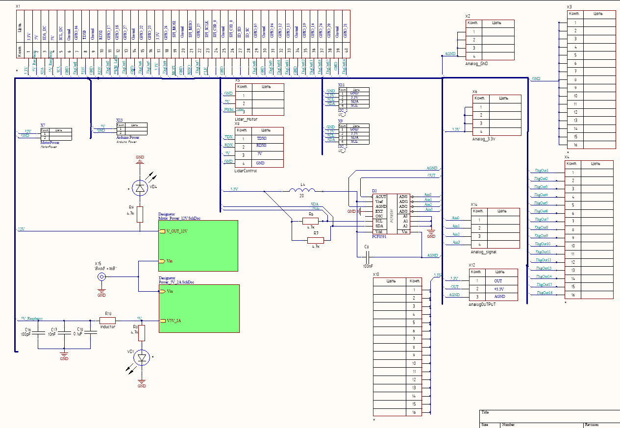
The following figure 4 shows the schematic diagram of the entire module, the voltage sources are shown here in the form of block diagrams
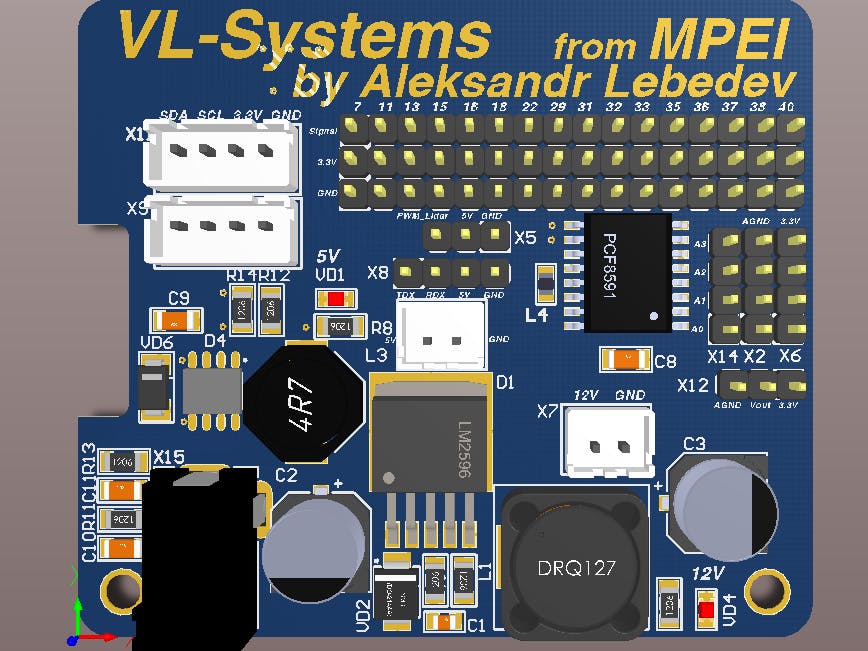
After the development of the circuit diagram begins the process of developing the PCB. To begin with, select the size of the future board, in this case it is 65x56mm, this size is selected from the size of the microcomputer Raspberry Pi 3, so that the module does not go beyond the dimensions of the main board.
Since all components are SMD and most of them are 1206 format, it is possible to compact placement of all components on the PCB. A very important point is the separation of the analog and digital parts of the electrical components so, for example, for the ADC should make a separate analog ground[4], that would interfere with the digital components do not affect the operation of the ADC. Filter elements (capacitors) should also be placed in close proximity to the inputs of the chips, this must be done to improve the efficiency of the filters.
After placing the components, the printed circuit board is traced in Fig.5 and Fig.6 shows the upper and lower layers of conductors, respectively.
The appearance of the finished board is shown in Fig.7.
After installation of all components, no errors were found. It can be concluded that all calculations were correct, and the topology is correct. This module has been tested on a mobile robot and we can make a conclusion about its suitability for construction of other mobile robots on the basis of the microcomputer Raspberry Pi 3. The development of the electrical circuit and printed circuit board of this module was carried out in Altium Designer 17[5].
All PCB i order on PCBWay
And now PCBWay have 5th anniversary activity if you want to get Assembly activity $ 30 link to this https://www.pcbway.com/anniversary5sales.html


Comments
Please log in or sign up to comment.