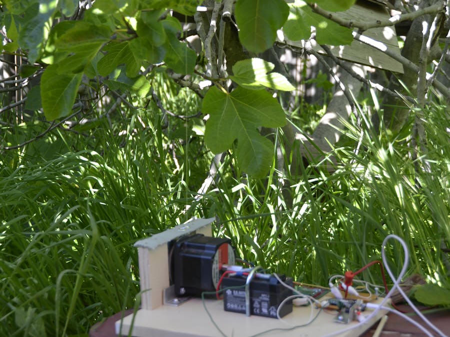
The project uses a stepper motor to pull down on a fig tree limb to frighten away birds and squirrels. That is, shake the limb.
I know that shaking a limb frightens birds and squirrels well, because I have done so using a hand-operated fishing line attached to a limb.
I programmed the MKR1000 to shake the limb in a simple pattern.
One cycle is defined as one pull-down, or one release upward, on the line by the stepper motor, that is the motor moves in one direction for the pulldown and the other direction for the release upward.
A pair of cycles is one pull-down and one release upward of the limb.
My original plan was more extensive than I had time for, owing to different setbacks. It was to be the following.
The cycles will be in sets, like 5 pairs per set, a pause, and then another set of 5 pairs.
This would be called a sequence. This kind of sequence I know works from experience.
After a period of ½ hour, another sequence occurs.
The cycles submitted in the report will be described.
The stepper motor sequence submitted in the report consists of eight changes of direction and four steps within each change of direction.
This sequence constitutes one execution.
Each execution is begun by instituting manually a microcontroller reset.
The initial plan had a series of executions under control by the MKR1000
The upper waveform shows direction. When the voltage is 3.3 V the motor rotates CCW and when the voltage is 0.0 V, the motor rotates CCW. The lower waveform shows the steps. When the voltage changes in the positive direction , the motor steps. We can observe four steps within each direction. The step period in this photo is 20 ms. (I used 10 ms finally.)
Digital I/O
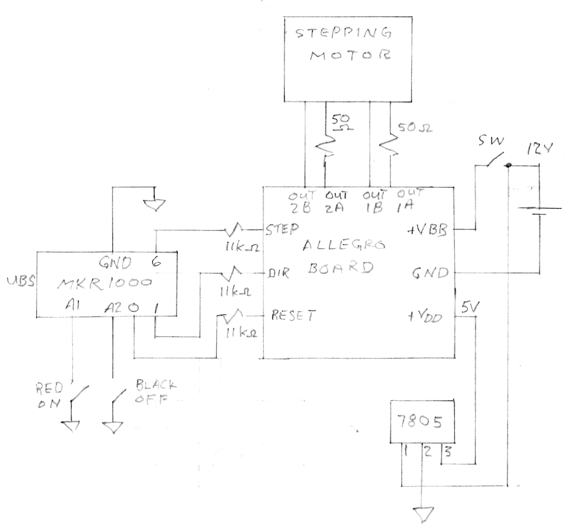
motor step pin 6
motor direction pin 1
motor driver reset pin 0
interrupts pins A1 and A2
Parameters to change to optimize the sequence for frightening birds and squirrels and values used in this report
time for ½ step period T0 = 5 ms
time for one direction T1 = 80 ms
time for one cycle T2 = 1280 ms
Bill of MaterialsA sample of reasons for which my project was delayed:
Initially, I burned out two motor driver chips. By the time I had ordered and installed the two chips, two weeks had elapsed.
When I tried to install interrupts, I discovered through the forum, that one of the attach functions was buggy. That took 1 ½ days.
I used many hours to try and get Serial.print to work. I finally gave up. The forum indicated that serial.print did not work as well.
In two other instances, I had a program written following all the coding guidelines, but the results were buggy. I have a feeling that I was violating some undocumented bug.
In the past, I coded to control this stepper motor using software for the Atmega 16 microcontroller. This is more versatile, developed software, which is nice but outside our rules for this MKR100 project, and more importantly for time savings, it is stable.
But, maybe we should expect bugs using this Beta version of the MKR1000.
Source Code/* Step and direction
Steps the motor in one direction, then steps it in the other direction.
the purpose of this code is a simple test of the power driver and MKR1000
The circuit:
STEP is from pin 6 to Allegro step.
DIRECTION is from pin 1.
RESET is from pin 0
created 3/29/16
by Art Wagner
*/
// constants won't change. Used here to set a pin number :
const int STEP6 = 6; // the number of the STEP pin
const int DIR1 = 1; // the number of the DIRECTION pin
const int RESET0 = 0; // the number of the RESET pin
// Variables will change : We are assigning initial digital values
int stepState = LOW;
int dirState = HIGH;
int resetState = HIGH;
unsigned long tT0; //previous time read for the step
unsigned long tT1; //previous time read for the directi
unsigned long tT2; //
const long T0 = 5; //T0 is the time between change in step signal. 10 10 5 2
const long T1 = 80; //T1 is the time between change in dir signal. 40 80 80 80
const long T2 = 1280; //T2 should give 4 direction changes 160 320 640 640 640
void setup() {
//start serial connection
Serial.begin(9600);
//the first t p.o. is 801 ms
// set the digital pins as outputs:
pinMode(STEP6, OUTPUT);
pinMode(DIR1, OUTPUT);
pinMode(RESET0, OUTPUT);
//Allows the driver to accept commands, begin this in setup
digitalWrite(RESET0, 0); //RESET = HIGH = OPERATE Keep RESET = 0 to inhibit current to motor
//Make sure step is low
digitalWrite(STEP6, stepState); //begin with step low
digitalWrite(DIR1, dirState); //begin with dir high
digitalWrite(RESET0, resetState); //begin with reset high
tT0 = millis(); //initialize for delta calc
tT1 = millis(); //initialize for delta calc
tT2 = millis(); //initialize for wait
}
void loop() {
//delay(3000); //allows me to remove my hand after resetting
//STEP
//Serial.println(11);
//Serial.println(millis());
//Serial.println(tT0);
//Serial.println(T0);
//ONE
if (millis() - tT0 >= T0) //greater than or equal to
{
// save the new reference for step change
tT0 = millis();
// reverse sign of stepState
if (stepState == LOW) {
stepState = HIGH;
} else {
stepState = LOW;
}
// set step pin with the current step state:
digitalWrite(STEP6, stepState); //doesn't do this until the if statement is TRUE
}
//DIRECTION
// TWO
if (millis() - tT1 >= T1)
{
// save the new reference for direction
tT1 = millis();
// reverse the sign of dirState:
if (dirState == LOW) {
dirState = HIGH;
} else {
dirState = LOW;
}
// set dir pin with the new dir state:
digitalWrite(DIR1, dirState);
}
//WAIT
// THREE
// if(millis() - tT2 >= T2){
// digitalWrite(RESET0,LOW);
// }
while(millis() - tT2 >= T2){
}
}


Comments
Please log in or sign up to comment.