//FIERO ALDL SCAN TOOL FOR 1987-88 ECMs
//Designed by Michael Walker
//Burleson, Texas
//Copyright 2022-2023.
//Revision A: Improved the O2 voltage value by multiplying by 0.0044 instead of dividing by 226 so that smaller
// values would not be returned as 0V.
//Free and Open Source Rights: This hardware and firmware design is provided without cost or renumeration of
//any kind and may used for any purposes with the following restrictions;
//1. The design is provided with no warranty expressed or implied and you use this design at your own risk.
// The author assumes no responsibility for the use of it or of any consequences.
//2. The design may not be sold or used for ANY COMMERCIAL use what so ever! It is free to anyone and no one
// may use the design for their own monetary or personal benefit. It is for the general automobile
// community at large and requires no compensation.
//3. The design may be altered as you desire for your own use however ANY DISTRIBUTION of the changed design
// MUST credit the original author and the altered design may NOT be sold or used for ANY COMMERCIAL use.
//The ALDL Scan Tool is designed to work with the 87-88 Pontiac Fiero and other GM vehicles that use the
//1227748 ECM (or similar). This code is specific to the Fiero 2.5 and other cars that use the 2.5 Iron
//Duke engine and Isuzu 5 speed manual transaxle. It is easily modified to include the values, such as
//TCC for an automatic transaxle. See the DESIGN NOTES document for details.
//NOTE that this hardware and program will work for virtually any GM ECM that utilizies the 8192
//Baud rate and protocol; the difference between the 2.5 Fiero and other usages is in the meaning of the data
//returned. There are several websites available that detail the data coding for various engines/cars, such as
//the websites devoted to "TunerPro" and other tools that should help you to adapt this to other uses. I am not
//involved in the TunerPro and TunerPro RT products in any way.
//Disclaimer:
//To be honest, I was only interested in the Fiero because this is my personal car. I have used and definitely
//recommend TunerPro RT for analysis and repair of GM cars; frankly, it is a superior tool to mine in the fact
//that it can be used for extreme tuning and datalogging which I do not support with this tool. The disadvantage
//of TunerPro is the need for a laptop (or in some implementations a cell phone app) to use it. This is fine for
//analysis at home in the comfort of your garage yet I wanted a tool that could travel with the car and not
//require much else for diagnosis. Plus, I'm an electrical engineer with decades of hardware and firmware design
//experience and wanted to play. Admittedly this is a somewhat crude adaptation tool because I didn't
//want to spend a lot of time and money on something I considered a "nice to have" and I wanted it to be cheap and
//easy enough for a person with average electronic skills to build and program should they want one as well. Most
//people have a need to diagnose failures and little else so this is perfect for that. Also beats reading "blinks"
//when you need to know what code set off the "check engine" or "service engine soon" lamp.
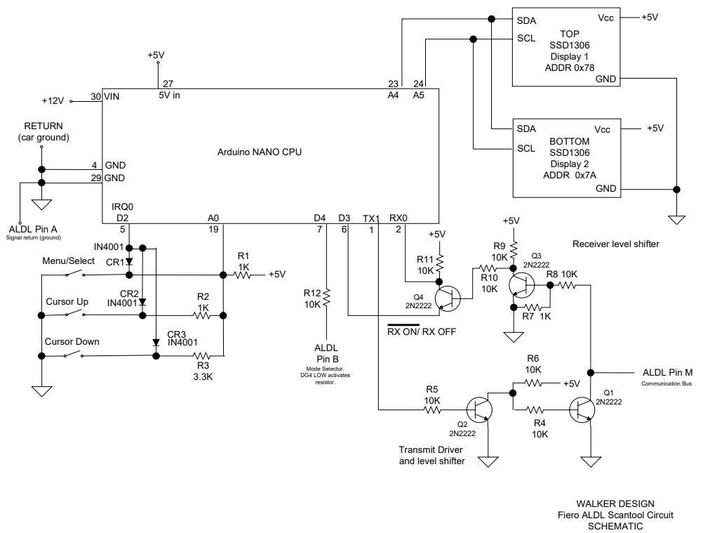
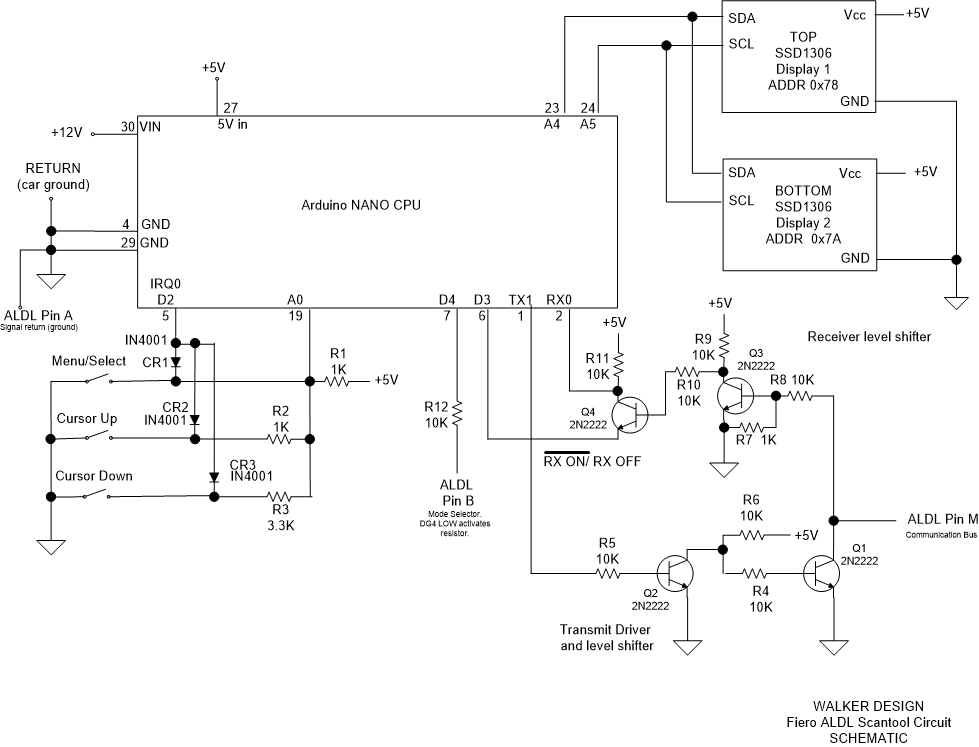
//The design is based on the readily available Arduino NANO simply because the ARDUINO series of microcontrollers
//are so easy to use and understand for the average person interested in electronics. The "Wiring" language, although
//based on the 'C' language, is quite simple and the available libraries make it an exceptional tool for the beginner
//and expert as long as the application doesn't require a high-speed implementation. Serial communications rarely
//if ever, warrants performing a "bare-metal" high speed implementation so use of something more difficult and
//expensive, such as a Zynq processor, etc. isn't warranted and is beyond most hobbyists. I have literally 35+
//years experience with those systems and could have used them...but again, cheap and easy is the idea. I wanted
//others to have fun with this as well. Other Arduino devices could also be used as long as you modify the code to
//use the definitions required for the other device. At the time the NANO was the smallest, simplest, cheapest,
//available from dozens of sources and is more than up to the task.
//The design "as is" will allow you to communicate with the 8192 baud rate ECMs; only the routines that display
//the data in a "human-readable" format will need to be revised for your car's format which is simple once you study
//how it works and have the definition file for your car...which is often available from the TunerPro website (and others).
#include <Arduino.h>
#include <U8x8lib.h>
#include <Wire.h>
#ifdef U8X8_HAVE_HW_SPI
#include <SPI.h>
#endif
#define MS 1 //menu/select button
#define UP 2 //Cursor Up button
#define DN 3 //Cursor Down button
//The U8x8 library is part of the U8g2 library and is text-only operation. This prevents using a graphics
//buffer for each display which takes up virtually all of the NANO RAM! Text is obviously better for this.
//The Adafruit_SSD1306 library is more versatile EXCEPT it has a bug that prevents using more
//than one display! U8x8 is the way to go for this project.
//Define two displays:
U8X8_SSD1306_128X64_NONAME_SW_I2C TOP(/* clock=*/ SCL, /* data=*/ SDA, /* reset=*/ U8X8_PIN_NONE); // OLEDs without Reset of the Display
U8X8_SSD1306_128X64_NONAME_SW_I2C BOTTOM(/* clock=*/ SCL, /* data=*/ SDA, /* reset=*/ U8X8_PIN_NONE); // OLEDs without Reset of the Display
//The Nano uses Asynchronous Double Speed mode by default for the serial port. This means the baud rate
//register equation is 16Mhz / (8 x baudrate) -1. To get 8192 baud the value of 243 must be written to
//the baud rate register UBRRn. The Arduino header file defines the register with a macro as UBRR0.
//After experimenting with this I was able to prove that using 8192 directly in the Serial.begin() command
//accurately programs the baud rate without any additional manipulation.
//Data for the xmit message to the Fiero ECM.
// 0xF0; //start message, LSN is message ID. Using 0 every time to simply the code by not generating IDs.
// 0x56; //# of message words (1) + 85 per GM protocol. 86 = 0x56. NOTE: GM refers to each BYTE as a WORD!
// 0x01; //the data word which contains Mode 1 (10K) mode which includes all data from ECM
// 0xB9; //2's complement of checksum
//This is stored in outbuffer. Array inbuffer contains the raw data returned from the Fiero ECM.
//Many Global variables are used because they are shared with multiple routines.
//Normally I avoid using globals because it is bad practice...but in this case it seemed clearer than passing
//the variables with each call. This makes it much easier for an amateur programmer, i.e. a
//hobbyist to follow. The program is small enough that optimization isn't necessary so this approach is fine.
//All of the "expert" programmers out there can refrain from critiquing the code because I know. I made it simple
//to understand ON PURPOSE. I could have written it in Assembly in my sleep but that helps no one else.
//FYI I taught Firmware Development in after-hours college level classes for several years and I've heard enough
//"critique" from "experts" in forums to last a lifetime. Accept it as-is; I have no wish to revise it to someone
//else's opinion since it works quite well. This was a fun experiment, don't try to make it hard.
byte outbuffer[5]={0xF0,0x56,0x01,0xB9}, inbuffer[130], checksum;
int button, buttonRef, menuVal, upVal, downVal, change, Cursor, current_display;
int tenK, F_RT, Raw, start, prior, bytecount,m, I, found, cs_flag;
unsigned long st_time, end_time, ms_loop;
//string constants that are stored in Flash. The "F("") encapsulation tells the compiler/linker to place
//the data between the quotation marks into Flash memory.
#define BLANKLINE F(" ")
#define Y F("Y")
#define N F("N")
#define SPACE F(" ")
#define ZERO F("0")
//Interrupt service routine for the three buttons: menu/select, cursor up and cursor down
//For simplest debounce logic, the buttons function by holding them down until you see a change on the display(s).
//Releasing the button "resets" the logic such that the next press can be entered. A little slow but speed
//isn't really required for this and a proper debounce circuit would have added a great deal to the size of the
//circuit for little improvement. I was going for quick design, simple, and cheap.
//The interrupt is released when the button is released after the change is seen on the display(s)
void buttonISR()
{
int i, count[10], strikeMS =0, strikeUP=0, strikeDN=0;
//initialize button to 0
button = 0;
noInterrupts();//stop button presses generating interrupt. Will be enabled after change is processed.
//get 10 samples of the button pressed
for(i = 0; i<10;i++) count[i] = analogRead(A0);//read 10 voltage divider samples
//get the strike count for each sample; the most samples equals the correct button
for(i=0; i<10; i++)
{
if (count[i] < menuVal) strikeMS++;
if ((count[i] > menuVal) && (count[i] < upVal)) strikeUP++;
if ((count[i] > upVal) && (count[i] < downVal)) strikeDN++;
}
if ((strikeMS > strikeUP) && (strikeMS > strikeDN)) button = MS;
if ((strikeUP > strikeMS) && (strikeUP > strikeDN)) button = UP;
if ((strikeDN > strikeMS) && (strikeDN > strikeUP)) button = DN;
//set the change request flag
change = 1;
}
//The Main Menu appears on the top display and is provided by this routine. The menu provides the user several
//options prior to requesting data from the ECM.
//10K Mode: The Fiero ECM provides data in three defined packet structures (others may use more modes): Mode 0
//(22 bytes of data), Mode 1 (63 bytes of data) and Mode 2 (22 bytes of data). Mode 0 is requested using an open
//circuit on pin M of the ALDL. Mode 1 is provided by connecting a 10K resistor on pin M. Mode 2 is requested
//using a short circuit on pin M. I chose to implement Mode 1 only because it provides the most data using the
//10K resistor. The menu provides the option to select the 10K mode or open mode although
//I have not programmed any code for open so this is a future option if you choose. Default is 10K mode
//Frame/Realtime Mode: This allows the user to request a single frame of data or a continuous stream of frames
//in "real time". Single frame mode means you must return to the menu and request another frame of data when
//you are ready. Realtime mode means once you request data frames the dat will continue and update the displays
//every few seconds until you select to return to the menu. NOTE that "real time" is a misnomer because the ECM
//has a latency on most data of 1 to 1.5 seconds so you won't actually get data in real time but it will be
//updating automatically in that mode. Realtime mode is the default.
//Raw Data Mode: This is mainly a debugging tool yet it is useful if you wish to learn the protocol of the data.
//This selection displays the 66 bytes returned from the ECM in a single frame for debugging purposes. You can
//also use this to see that the ECM is actually returning data. The buffer is cleared to all zeros prior to
//receiving data so displays of all zeros indicate no data was returned. A proper frame will start with the
//protocol "echo" bytes of "F0 95 01" followed by the data that defines the engine management values. These
//bytes are then converted to the physical values that are "human readable" in the other modes but here they are
//shown as the computer "sees" them. The default is NO to this mode. The checksum, calculated checksum and the
//result, either OK or BAD are at the bottom of the display.
//Start: This selection executes your menu choices and begins communication with the ECM. The display will
//indicate "GO" when executed and the displays will change to the data displays.
void menu()
{
//This routine is called any time the Main Menu is requested
TOP.setCursor(0,0);
TOP.print(F(" Main Menu \n"));
TOP.print(F(" Use 10K:"));
if(tenK)
TOP.print(F("Y \n"));
else
TOP.print(F("N \n"));
TOP.print(F(" Frame/RT:"));
if(F_RT)
TOP.print(F("RT \n"));
else
TOP.print(F("F \n"));
TOP.print(F(" Raw Data:"));
if(Raw)
TOP.print(F("Y \n"));
else
TOP.print(F("N \n"));
if(start)
TOP.print(F(" Start GO \n"));
else
TOP.print(F(" Start \n"));
//clear remaining 3 lines
TOP.setCursor(0,5);
TOP.print(BLANKLINE);
TOP.setCursor(0,6);
TOP.print(BLANKLINE);
TOP.setCursor(0,7);
TOP.print(BLANKLINE);
//make sure Cursor value is within limits.
if (Cursor < 0) Cursor = 0;
if (Cursor > 3) Cursor = 3;
//clear any previous cursor from display
TOP.setCursor(0,Cursor);
TOP.print(SPACE);
//now print the current cursor on the display
TOP.setCursor(0,Cursor + 1);//this should initialize cursor at Start based on initial Cursor value in setup
TOP.print(F(">")); //use this as a cursor.
BOTTOM.clearDisplay();
current_display = 0; //indicate Main Menu in value
}
//The setup() routine is the standard Arduino process for initializing functions and hardware settings. At
//completion the routine calls the Main Menu.
void setup()
{
pinMode(2, INPUT_PULLUP);//interrupt input for buttons.
pinMode(3, OUTPUT);//RX control, LOW to activate, HIGH for TX. Connected to digital pin 3.
digitalWrite(3, HIGH); //initialize RX to OFF, TX mode.
pinMode(4, OUTPUT);//10K resistor is connected to digital pin 4.
change = 0; //clear the change request flag
Cursor = 3; //set the Cursor position value for "Start" menu item
current_display = 0; //set to Main Menu value
button = 0; //clear button so that none are indicated
tenK = 1; //default 10K use to Yes
F_RT = 1; //default Frame/Realtime to Realtime
Raw = 0; //default raw data to No.
start = 0; //default start communication to No
//MUST SET THIS UP TO GET BOTH DISPLAYS TO FUNCTION CORRECTLY!!!!!!
//IF YOUR DISPLAYS HAVE DIFFERENT ADDRESSES THEN MODIFY THESE VALUES ACCORDINGLY.
//NOTE THAT *SOME* ARE MARKED WITH 0X3C AND 0X3D WHICH IS HALF OF THESE VALUES, I.E. 0X78 / 2 = 0X3C.
//THAT IS BECAUSE I2C WAS ORIGINALLY A 7 BIT INTERFACE AND LATER UPDATED TO 8 BIT, I.E. A 1 BIT SHIFT IN BINARY
//IS THE SAME AS MULTIPLYING BY 2. ANY I2C DEVICE CAN WORK WITH THIS BUT IT IS UP TO THE PROGRAMMER TO DETERMINE
//WHICH ADDRESSING METHOD YOU USE! IT IS EASIER IF YOU USE TWO IDENTICAL DEVICES RATHER THAN TRYING TO USE
//DIFFERENT DISPLAYS SINCE IT MAY COMPLICATE PROGRAMMING. YOU will NEED TWO VALID ADDRESSES SO YOU WANT A DISPLAY
//THAT SUPPORTS PLACING IT ON UNIQUE ADDRESSES, USUALLY THROUGH A SOLDER JUMPER OR MOVING A RESISTOR/JUMPER.
//ONCE YOU HAVE ONE DISPLAY WORKING YOU WILL NEED TO MODIFY THE SECOND TO BE ON A DIFFERENT ADDRESS.
// Mine required 0x78 and 0x7A to work despite being labelled as 0x3C and 0x3D on the board silkscreen.
TOP.setI2CAddress(0x78);
BOTTOM.setI2CAddress(0x7A);
TOP.begin();
TOP.setPowerSave(0);
TOP.setFont(u8x8_font_chroma48medium8_r);
BOTTOM.begin();
BOTTOM.setPowerSave(0);
BOTTOM.setFont(u8x8_font_chroma48medium8_r);
//Set USART to Fiero ECM baud rate of 8192
Serial.begin(8192);
//calibrate the button voltage divider so that variances in 5V will be ignored.
//Menu-Select should always be 0 so any small value will work for that button.
//Cursor Up uses a 1K to 1K ratio so any value approximating half-scale plus tolerance is OK.
//Cursor Down uses a 3.3K to 1K so any value approximating one-third scale plus tolerance is OK.
buttonRef = analogRead(A0);
menuVal = 100; //if less than 100 then MS was pressed.
upVal = buttonRef / 1.9; //if less than this value then Cursor Up was pressed
downVal = buttonRef / 1.2; //if less than this value then Cursor Down was pressed
attachInterrupt(digitalPinToInterrupt(2), buttonISR, FALLING);
interrupts(); //enable the interrupt
//Initialize the displays using Main Menu routine
menu();
}
//The Arduino main loop will monitor the change request flag. If the button ISR sets the flag then the loop
//will process the changes needed. The Menu/Select button will either bring up the Main Menu or will
//select a choice if the Main Menu is already being displayed. The Cursor Up/Down buttons will scroll
//through the display screens as required until the Menu/Select button is pressed and therefore reverting
//to the Main Menu. The Cursor Up/Down will move the cursor on the Main Menu to the available choices and
//pressing Menu/Select will act on the value that is indexed by the Cursor.
void loop()
{
if(change)
{
noInterrupts();
if(button == UP) Cursor--;
if(button == DN) Cursor++;
if((current_display != 0) && (button == UP))
{
current_display--;
if (current_display < 1) current_display = 1; //go to previous display of data or stay on first
}
if((current_display != 0) && (button == DN))
{
current_display++;
if (current_display > 3) current_display = 3; //go to next display of data or stay on last
}
//if already on Main Menu then update Cursor position
if((current_display == 0) && (button != MS)) menu();
//if on Main Menu and MS pressed then choice was selected therefore evaluate it
if((current_display == 0) && (button == MS))
{
switch (Cursor)
{
case 0:
if(tenK) tenK = 0; else tenK = 1; //toggle 10K resistor setting
break;
case 1:
if(F_RT) F_RT = 0; else F_RT = 1; //toggle Frame/Realtime setting
break;
case 2:
if(Raw) Raw = 0; else Raw = 1; //toggle Raw Data setting
break;
case 3:
if (start) start = 0; else start = 1; //flag to start communication
break;
}
menu(); //call menu to update the selection
}
//if on any display other than Main Menu, then the MS button returns to the menu
if((current_display != 0)&& (button == MS))
{
start = 0;//stop collecting data
Cursor = 3;//set to "start"
menu();
}
//Connect 10K resistor low side to return if selected else let it float to 5V
if(tenK)
digitalWrite(4,LOW);//connect it
else
digitalWrite(4, HIGH);//disable it
change = 0; //clear the change request flag
interrupts(); //enable the button interrupt
} //end of if(change)
//get the data from the ECM, either once for Frame or continuously for Realtime (default).
//the logic of this section allows the data to be updated continuosly as long as the "start" flag
//is set. It will only display the Raw data or the single frame display ONCE because the start flag
//is cleared for those choices after the data is gathered.
if(start)
{
found = 0; //clear the "data found in buffer" flag
while(found < 3) //while loop allows three tries to find the data in the buffer
{
//flush the receiver buffer
for(bytecount = 0; bytecount < 130; bytecount++) inbuffer[bytecount] = 0;
m = 0; //index for where the data is stored in the buffer
digitalWrite(3, HIGH); //disable RX so transmit can occur
if(Serial.available() > 0) Serial.read(); //clear out the Serial library input buffer to prevent any garbage
Serial.write(outbuffer, 4);//send the command to the Fiero ECM
digitalWrite(3, LOW); //enable RX
//now get the data in the huge buffer and parse the data into the beginning of the buffer.
//The first three bytes should be F0 95 01.
Serial.readBytes(inbuffer, 130);//receive command echo followed by 63 data bytes in a HUGE buffer
for(bytecount = 0; bytecount < 64; bytecount++) //need to find it before the last 66 bytes of the buffer
{
if((inbuffer[bytecount] == 0xF0)&&(inbuffer[bytecount+1] == 0x95)&&(inbuffer[bytecount+2] == 0x01))
{
m = bytecount;
found = 3;//found it, get out
break;
}
}
found++; //increment attempt counter. Bogus data = timeout. Aids debugging when not connected to the ECM.
}// end of while(found < 3)...
digitalWrite(3, HIGH); //disable RX to stop ECM data from coming in while processing the data
//now use index "m" to move the data to the beginning of the buffer. Include one extra byte that should contain
//the ECM checksum.
for(bytecount = 0; bytecount < 67; bytecount++)
{
inbuffer[bytecount] = inbuffer[bytecount + m];
}
//accumulate the checksum of all the data bytes except the checksum but including the header.
checksum = 0;
cs_flag =1;// force it to BAD until proven good
for(I = 0; I<65; I++) //add all EXCEPT checksum
{
checksum+=inbuffer[I];
}
checksum&=0xFF;//clear overflow so that value is 0xFF or less
if(((0xFE - inbuffer[66])&0xFF) == checksum) cs_flag = 0;//if good, clear the flag
if(current_display == 0) current_display = 1; //if on main menu, set to first data display
if ((F_RT == 0)||(Raw == 1)) start = 0; //single frame, stop getting data after first set
//determine the data to display based on the current_display value with 1 = to the first data.
//These are updated in "real time".
//NOTE: if you wish to add more displays then modify the "switch" statement to add calls after
//the "case 3" block. You will then need to create the routines that contain your new displays.
//See the next section and the functions later in this file for examples of how to write those routines.
switch(current_display)
{
case 0://do nothing for main menu. Shouldn't happen so this is just an error catch-all
break;
case 1:
if(Raw) raw_data(); else first_data(); //display either first data or raw data on both displays
prior = 1; //save the last choice for the F_RT processing
break;
case 2:
second_data(); //display second set of data on both LED displays
break;
case 3:
third_data(); //display third set of data on both LED displays
break;
}
} //end of if(start)
//this next logic allows the Frame data displays to be shown. The previous logic will only show the
//first data display because the start flag is cleared thereby preventing the calling of the three display
//choices. This logic is triggered by the F_RT flag so that all three data sets can be rotated through
//the screens. Not the best way to do this yet I didn't want to add "while(1)" statements and
//the error trapping that would require on such a simple program.
if((F_RT == 0) && (current_display != 0)) //Frame mode selected
{
//determine the data to display based on the current_display value with 1 = to the first data.
//These are not updated, they only display the previously acquired data again. You must enter the
//Main Menu again to acquire new data in single Frame mode.
//Do not re-print the display if the current_display is the same as the prior display. Only print the
//display again if the current_display changed. This will prevent "flickering" of the screen.
//NOTE: if you wish to add more displays then modify the "switch" statement to add calls after
//the "case 3" block here as well.
if (current_display != prior)
{
switch(current_display)
{
case 0://do nothing for main menu. Shouldn't happen so this is just an error catch
break;
case 1:
first_data(); //display either first data or raw data on both displays
prior = current_display; //save the selection for the next loop
break;
case 2:
second_data(); //display second set of data on both LED displays
prior = current_display; //save the selection for the next loop
break;
case 3:
third_data(); //display third set of data on both LED displays
prior = current_display; //save the selection for the next loop
break;
}//end of switch(current_display)
} //end of if(current_display != prior)
} //end of if(F_RT == 0)
}// end of main loop
//Routine first_data() displays the first 16 lines worth of the calculated values from the Fiero ECM.
//Each display contains 8 lines and EACH LINE IS 16 CHARS LONG with the first character at position 0l
//Values are calculated from the data returned in "inbuffer".
void first_data()
{
TOP.setCursor(0,0); //NOTE THIS FUNCTION IS COLUMN, ROW !!!
if(cs_flag !=0) //if not 0 then a data error occurred because the checksum was wrong
{
TOP.print(F("***DATA ERROR***"));
}
else //checksum was good, display the new data
{
TOP.print(F("DTC SET? "));
TOP.setCursor(11,0);
//check to see if any DTC values are set and if so, then tell me
if ((inbuffer[5] == 0) && (inbuffer[6] == 0) && (inbuffer[7] == 0))
TOP.print(F("NO "));
else
TOP.print(F("YES!"));
TOP.setCursor(0,1);
TOP.print(F("CTS F"));
TOP.setCursor(4,1);
TOP.print(inbuffer[8] * 1.35 -40);
TOP.setCursor(0,2);
TOP.print(F("TPS V"));
TOP.setCursor(4,2);
TOP.print(inbuffer[10] * 0.0196);
TOP.setCursor(0,3);
TOP.print(F("RPM "));
TOP.setCursor(4,3);
TOP.print(inbuffer[12] * 25);
TOP.setCursor(0,4);
TOP.print(F("Tgt RPM "));
TOP.setCursor(8,4);
TOP.print(inbuffer[25] * 12.5);
TOP.setCursor(0,5);
TOP.print(F("O2 V"));
TOP.setCursor(3,5);
TOP.print(inbuffer[17] * 0.0044); // value/226, multiply by inverse so > 0 for all returned values.
TOP.setCursor(0,6);
TOP.print(F("O2 R/L Cnt "));
TOP.setCursor(11,6);
TOP.print(inbuffer[18]);
TOP.setCursor(0,7);
TOP.print(F("RICH/LEAN "));
TOP.setCursor(10,7);
if((inbuffer[57] & 0x40) == 0x40)
TOP.print(F("Rich"));
else
TOP.print(F("Lean"));
//now the bottom display
BOTTOM.setCursor(0,0); //NOTE THIS FUNCTION IS COLUMN, ROW !!!
BOTTOM.print(F("O2 RDY "));
BOTTOM.setCursor(14,0);
if((inbuffer[63] & 0x01) == 0x01)
BOTTOM.print(Y);
else
BOTTOM.print(N);
BOTTOM.setCursor(0,1);
BOTTOM.print(F("Closed Loop "));
BOTTOM.setCursor(14,1);
if((inbuffer[57] & 0x80) == 0x80)
BOTTOM.print(Y);
else
BOTTOM.print(N);
BOTTOM.setCursor(0,2);
BOTTOM.print(F("BLM "));
BOTTOM.setCursor(4,2);
BOTTOM.print(inbuffer[20]);
BOTTOM.setCursor(0,3);
BOTTOM.print(F("INT "));
BOTTOM.setCursor(4,3);
BOTTOM.print(inbuffer[22]);
BOTTOM.setCursor(0,4);
BOTTOM.print(F("BARO V"));
BOTTOM.setCursor(6,4);
BOTTOM.print(inbuffer[27] * 0.0196);
BOTTOM.setCursor(0,5);
BOTTOM.print(F("MAP(P) V"));
BOTTOM.setCursor(8,5);
BOTTOM.print(inbuffer[28] * 0.0196);
BOTTOM.setCursor(0,6);
BOTTOM.print(F("MAPld KPa"));
BOTTOM.setCursor(7,6);
BOTTOM.print(inbuffer[29] / 3.2);
BOTTOM.setCursor(0,7);
BOTTOM.print(F("MAT F"));
BOTTOM.setCursor(5,7);
BOTTOM.print(inbuffer[32] * 1.35 -40);
}
}
//Routine second_data() displays the second 16 lines worth of the calculated values from the Fiero ECM.
//Values are calculated from the data returned in "inbuffer".
void second_data()
{
int index, tempval;
if(cs_flag !=0) //if not 0 then a data error occurred because the checksum was wrong
{
TOP.print(F("***DATA ERROR***"));
}
else //checksum was good, display the new data
{
TOP.setCursor(0,0); //NOTE THIS FUNCTION IS COLUMN, ROW !!!
TOP.print(F("IAC now "));
TOP.setCursor(10,0);
TOP.print(inbuffer[23]);
TOP.setCursor(0,1);
TOP.print(F("IAC Tgt "));
TOP.setCursor(10,1);
TOP.print(inbuffer[24]);
TOP.setCursor(0,2);
TOP.print(F("BATT V"));
TOP.setCursor(6,2);
TOP.print(inbuffer[34] / 10);
TOP.setCursor(0,3);
TOP.print(F("BATT Overvolt? "));
TOP.setCursor(15,3);
if((inbuffer[7] & 0x04) == 0x04)
TOP.print(Y);
else
TOP.print(N);
TOP.setCursor(0,4);
TOP.print(F("Spk Adv D"));
TOP.setCursor(9,4);
TOP.print(inbuffer[35] * 0.3515);
TOP.setCursor(0,5);
TOP.print(F("Spk Adv "));
TOP.setCursor(9,5);
tempval = inbuffer[36] * 256 + inbuffer[37];
if((inbuffer[36] & 0x80) == 0x80) //negative therefore retarded timing
TOP.print((65536 - tempval) * 0.3516);
else
TOP.print(tempval * 0.3516); //positive therefore advanced timing
TOP.setCursor(0,6);
TOP.print(F("BPW ms"));
TOP.setCursor(5,6);
TOP.print((inbuffer[38] * 256 + inbuffer[39]) / 65.536);
TOP.setCursor(0,7);
TOP.print(F("Tgt A/F "));
TOP.setCursor(9,7);
TOP.print(inbuffer[40] / 10);
//now the bottom display shows the DTCs that are set, up to 7 lines worth.
BOTTOM.setCursor(0,0); //NOTE THIS FUNCTION IS COLUMN, ROW !!!
BOTTOM.print(F("DTC set, <8 "));
index = 1;
if ((index < 8) && (inbuffer[5] & 0x01))
{
BOTTOM.setCursor(0, index);
BOTTOM.print(F("24 VSS "));
index++;
}
if ((index < 8) && (inbuffer[5] & 0x02))
{
BOTTOM.setCursor(0, index);
BOTTOM.print(F("23 MAT Low "));
index++;
}
if ((index < 8) && (inbuffer[5] & 0x04))
{
BOTTOM.setCursor(0, index);
BOTTOM.print(F("22 TPS Low "));
index++;
}
if ((index < 8) && (inbuffer[5] & 0x08))
{
BOTTOM.setCursor(0, index);
BOTTOM.print(F("21 TPS High "));
index++;
}
if ((index < 8) && (inbuffer[5] & 0x10))
{
BOTTOM.setCursor(0, index);
BOTTOM.print(F("15 CTS Low "));
index++;
}
if ((index < 8) && (inbuffer[5] & 0x20))
{
BOTTOM.setCursor(0, index);
BOTTOM.print(F("14 CTS High "));
index++;
}
if ((index < 8) && (inbuffer[5] & 0x40))
{
BOTTOM.setCursor(0, index);
BOTTOM.print(F("13 O2 Open "));
index++;
}
if ((index < 8) && (inbuffer[5] & 0x80))
{
BOTTOM.setCursor(0, index);
BOTTOM.print(F("12 No Ref Pulse "));
index++;
}
if ((index < 8) && (inbuffer[6] & 0x01))
{
BOTTOM.setCursor(0, index);
BOTTOM.print(F("42 EST Monitor "));
index++;
}
if ((index < 8) && (inbuffer[6] & 0x04))
{
BOTTOM.setCursor(0, index);
BOTTOM.print(F("35 IAC "));
index++;
}
if ((index < 8) && (inbuffer[6] & 0x08))
{
BOTTOM.setCursor(0, index);
BOTTOM.print(F("34 MAP Low "));
index++;
}
if ((index < 8) && (inbuffer[6] & 0x10))
{
BOTTOM.setCursor(0, index);
BOTTOM.print(F("35 MAP High "));
index++;
}
if ((index < 8) && (inbuffer[6] & 0x80))
{
BOTTOM.setCursor(0, index);
BOTTOM.print(F("25 MAT High "));
index++;
}
if ((index < 8) && (inbuffer[7] & 0x01))
{
BOTTOM.setCursor(0, index);
BOTTOM.print(F("55 SBus Error "));
index++;
}
if ((index < 8) && (inbuffer[7] & 0x10))
{
BOTTOM.setCursor(0, index);
BOTTOM.print(F("51 PROM Error "));
index++;
}
if ((index < 8) && (inbuffer[7] & 0x20))
{
BOTTOM.setCursor(0, index);
BOTTOM.print(F("45 O2 Rich "));
index++;
}
if ((index < 8) && (inbuffer[7] & 0x40))
{
BOTTOM.setCursor(0, index);
BOTTOM.print(F("44 O2 Lean "));
index++;
}
//blank out any remaining lines
for (tempval = index; tempval < 8; tempval++)
{
BOTTOM.setCursor(0, tempval);
BOTTOM.print(BLANKLINE);
}
}
} //end of second_data
//Routine third_data() displays the third 16 lines worth of the calculated values from the Fiero ECM.
//Currently only one line is used so if you wish to display further information this would be the easiest
//place to do it. See the previous data routines for examples of how you could modify this.
//Values are calculated from the data returned in "inbuffer".
void third_data()
{
int index, tempval;
if(cs_flag != 0) //if not 0 then a data error occurred because the checksum was wrong
{
TOP.print(F("***DATA ERROR***"));
}
else //checksum was good, display the new data
{
TOP.setCursor(0,0); //NOTE THIS FUNCTION IS COLUMN, ROW !!!
TOP.print(F("PROMID: "));
TOP.setCursor(10,0);
TOP.print(inbuffer[3] * 256 + inbuffer[4]);
//blank out any remaining lines
for (tempval = 1; tempval < 8; tempval++)
{
TOP.setCursor(0, tempval);
TOP.print(BLANKLINE);
}
BOTTOM.clear();
}
}
//Routine raw_data() displays the data received from the Fiero ECM without any calculations.
//The lines are filled with 5 bytes each in hexadecimal format and end with the checksum byte.
//The next to last line contains the calculated checksum from that last value and the bottom
//line contains the sum of the data values for comparison purposes and the results of the comparison,
//either "OK" or "BAD". This display is for debugging purposes as well as allowing you to manually
//calculate the engine management values to see if your calculations are reasonable. See the Design
//Notes or the source of your ECM data word descriptions if not using on a Fiero.
void raw_data()
{
int index, I, J;
TOP.clearDisplay();
BOTTOM.clearDisplay();
index = 0;
//place data, up to 40 bytes, on top display, line by line sequentially.
for(I = 0; I < 8; I++) //perform for each line in top display
{
TOP.setCursor(0,I); //NOTE THIS FUNCTION IS COLUMN, ROW !!!
for(J = 0; J < 5; J++) // five values per line
{
if (inbuffer[index] < 16) TOP.print(ZERO); //add leading 0 if only a single hex digit
TOP.print(inbuffer[index], HEX); //print the value in hexadecimal
TOP.print(SPACE); //add space between values
index++;
}
}
//place remaining data on bottom display, line by line sequentially.
for(I = 0; I < 8; I++) //perform for each line in bottom display
{
if (index > 66) continue; //finished all 66 bytes + checksum, do nothing more in this loop
BOTTOM.setCursor(0,I); //NOTE THIS FUNCTION IS COLUMN, ROW !!!
for(J = 0; J < 5; J++) // five values per line
{
if (index > 66) continue; //finished them all, do nothing more in this loop
if (inbuffer[index] < 16) BOTTOM.print(ZERO); //add leading 0 if only a single hex digit
BOTTOM.print(inbuffer[index], HEX); //print the value in hexadecimal
BOTTOM.print(SPACE); //add space between values
index++;
//reached the end of the data?
}
}
//display the checksum and results as OK or BAD
BOTTOM.setCursor(0,7); //NOTE THIS FUNCTION IS COLUMN, ROW !!!
BOTTOM.print(F("CS "));
BOTTOM.setCursor(3,7);
BOTTOM.print(checksum, HEX); //print the sum in hexadecimal
BOTTOM.setCursor(3,6);
BOTTOM.print((0xFE - inbuffer[65]), HEX);
//calculate the sent checksum value and evaluate whether correct or not and display results
BOTTOM.setCursor(7,7); //position for displaying results
if(cs_flag !=0)
{
BOTTOM.print(F("BAD"));
}
else
{
BOTTOM.print(F(" OK"));
}
}//end of raw_data
//end of file


Comments
Please log in or sign up to comment.