Hackster is hosting Hackster Holidays, Ep. 6: Livestream & Giveaway Drawing. Watch previous episodes or stream live on Monday!Stream Hackster Holidays, Ep. 6 on Monday!
walkertexan
Published © CC BY-NC-SA

Fiero Headlight Controller

Modern replacement for obsolete 87-88 Fiero headlight motor controller

IntermediateFull instructions provided20 hours701
Fiero Headlight Controller

Things used in this project

Hardware components

Arduino Nano
×1
acs712 30A
30A version of popular current sensor
×2
5VDC coil relay
SPDT small relays capable of 10A
×4
12VDC relay
SPDT small relay capable of 10A
×1
1N4001 diode
or equivalent
×1
2N2222A
or equivalent
×7
LED (generic)
LED (generic)
whatever color/size you want
×4
Through Hole Resistor, 200 ohm
1/8W or greater
×4
Resistor 1k ohm
Resistor 1k ohm
1/8W or greater
×7
Resistor 10k ohm
Resistor 10k ohm
1/8W or greater
×3
Linear Regulator (7805)
Optional; I prefer it yet you may use the Arduino Nano built-in regulator instead provided you modify the wiring appropriately.
×1
10 uF, 25V capacitor
Optional; only required if using optional 7805 voltage regulator
×2
connector
sold in pairs; I used these yet you may select another type if you wish. See documentation.
×2

Story

Read more

Schematics

Headlight Controller schematic in PDF file

allows you to understand and build the circuit

Headlight Controller installation using generic connectors

Allows you to connect the new controller in parallel with the original wires so you can use either one; ONLY ONE MAY BE INSTALLED at a time!

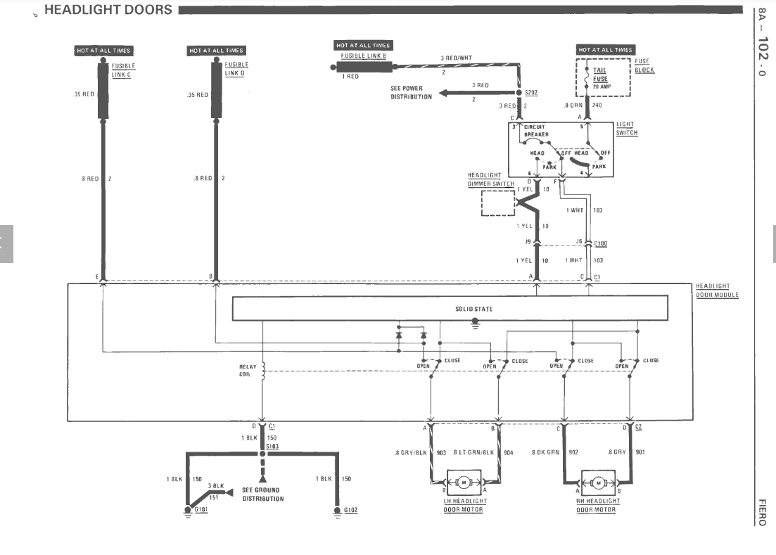
Headlight Door circuit in the car

reference for the original design to clarify the installation

Code

Fiero_Headlight_Door_Cont_V2_power_relay.ino

Processing
The final version of the software that includes use of the power relay to prevent any current draw when the doors are closed
//POWER RELAY version
//This program along with the circuitry replaces the Fiero Headlight Door Module with
//a modern equivalent.  The module in my car is dead so this has become a necessity.
//NOTE THAT THIS is a fix for 87 and 88 modules and NOT the prior design although
//it may be reasonably simple to implement for those if necessary.

//The Fiero Light switch produces two signals: one is at 12V when the lights are off
//while the other is at 12V when the lights are on.  Both are floating and essentially
//at ground potential when the parking lights are on.

//The original circuit performed a crude H bridge using a 4PDT relay which is an
//expensive component and hard to find in a format that fits the original module.  This
//approach uses four SPDT relays in an Arduino-compatible module to form the H bridge.
//The relay module is designed as active-low on the input signals.

//The original circuit used programmable logic to sense the current draw of each motor.
//If the motor stalled at either the ends or during travel then a high current would
//occur and the logic would remove power from the offending motor.  The relay in the
//circuit was limited to 5A so it is assumed that the maximum allowable continuous
//current was less than this.  Bad assumption.  GM did a poor design because the current
//is closer to 12A inrush as measured with an ammeter, although for short duration.  This explains
//the failed relays over the years and possibly causes the failures of the FETs.
//This approach uses two hall-effect Arduino-compatible current sensors to detect
//this condition so that power is removed quickly.

//The original circuit also provided a timer of approximately 2.5 seconds for the
//motors to reach either open or closed position.  This approach will do this as well.

//Program written by Michael Walker Copyright 03/2021.  Program is free for use without
//any warranty either expressed or implied.

int LH_zero_current, RH_zero_current; //values read to "calibrate" the current sensors
int Current_limit;
int count, Loop_count;
int current_value;
void Open_doors();//routine opens the doors and checks for damaging current
void Close_doors();//routine closes the doors and checks for damaging current


void setup()
{
  // pinitialization will occur when power is applied to the circuit through the 12V relay, i.e. when the
  //headlight switch is ON.  The lighting circuits have live power through that relay only.
  //TURN ON THE RELAY DRIVER IMMEDIATELY TO KEEP POWER ON THE CIRCUIT!  This driver allows the circuit
  //to remain ON when the switch is turned OFF long enough to retract the lights.
  //The circuit remains LIVE as long as the lights are ON once this is initiated; you must turn OFF the 
  //headlights in order to remove power from the circuit.

    pinMode(9, OUTPUT);//driver control for the 12V relay to power the module
    digitalWrite(9, HIGH);//keep the power ON until the doors are closed.
    
  //Keep this is mind when servicing any of the headlight components because they
  //can actuate at any time if the headlight switch is ON!
//  Serial.begin(9600);//debug and will probably be removed later.
//  Serial.println("Fiero Headlight Door Module V2 is Alive and Well!");

  //Current sensor ACS712/30A centers at 2.5V at zero current when operating with a 5V supply.  The
  //output is proportional to the current with 66mV equivalent to 1A.  The Arduino Nano A/D is 10-bit
  //so each count is 5/1024 or 4.88mV (14 counts per amp).  At zero current the value should be approximately 512.  A 5A
  //value should be approximately 5 * 66mV or 330mv.  That corresponds to a count of 330mV/4.88mV
  //which is approximately 68 counts above the zero current value. A value of 27 would be approximately
  //2A and 41 would be 3A.  Experimentation shows that the inrush current of the motor is approximately 
  //8A and sometimes triggers an overcurrent up to about 11A.  This means that the overcurrent level 
  //needs to be at least 12A and possibly more to account for ambient temperature.  A value of 14.8A
  //seems to give perfect results without overcurrent occurring and is low enough to prevent burnout of
  //the motor or the fuse links while accounting for higher current during cold conditions.
  //Increasing the delay time at initial startup to account for inrush might be a better approach since the
  //current limit could be lowered to a value closer to 8A and may be implemented in the future if it seems
  //prudent.
  Current_limit = 200; //approximately 14.8A above the "zero current" value to account for inrush current
  Loop_count = 150;  //number of loops with 10ms delay to equal 2.5 seconds. Accounting for A/D reads
                    //and logic every 10ms makes this number less than expected 250. Matches original system.
  //define the DIO pins
  pinMode(3, OUTPUT);//LH OPEN drive
  pinMode(4, OUTPUT);//LH CLOSE drive
  pinMode(5, OUTPUT);//RH OPEN drive
  pinMode(6, OUTPUT);//RH CLOSE drive
  pinMode(7, INPUT_PULLUP);//C1-C white wire CLOSE headlight switch signal
  pinMode(8, INPUT_PULLUP);//C1-A yellow wire OPEN headlight switch signal

  digitalWrite(3, LOW);   // turn off LH OPEN drive
  digitalWrite(4, LOW);   // turn off LH CLOSE drive
  digitalWrite(5, LOW);   // turn off RH OPEN drive
  digitalWrite(6, LOW);   // turn off RH CLOSE drive
 
  //Power has been applied so headlights were commanded. Open the doors.
  Open_doors();
  
}//end of setup

void loop()
{


  //The loop will check the condition of the two Headlight switch signals every
  //100ms.  The signals are active LOW to the circuit.

  //If DG7 is low and DG8 is high then the light switch is off so the doors are ordered CLOSED.
  if (digitalRead(7) == LOW && digitalRead(8) == HIGH)
  {
//       Serial.println("Light Switch is OFF ");//debug
    Close_doors();
  }

  delay(100);//wait 100ms before checking again
}// end of loop

void Open_doors()
{
  //This routine commands the LH and RH doors to OPEN and allows 2.5 seconds for
  //that to happen.  The current is monitored every 10ms and if it exceeds the
  //base zero current value plus/minus the high limit value then power is immediately
  //removed from the OPEN relay for the bad door.
  //The relays are turned off after the 2.5 seconds has
  //transpired unless turned off sooner due to overcurrent.

  //If the overcurrent only happens on one door then that door will likely be left
  //in a partially open state.  This allows you to detect which door was the problem
  //in case it isn't obvious for other reasons, like bad noises.  If nothing else
  //it allows you to crank the light to the proper position while the other remains
  //usable.

  Serial.println("Open Doors now");
    
  //no current should be present through the motors at this point so find the quiescent
  //value from the sensors
  LH_zero_current = analogRead(0); //this should be approximately 512 counts
  RH_zero_current = analogRead(1); //this should be approximately 512 counts
  Serial.print("Zero Current LH=");
  Serial.println(LH_zero_current);
  Serial.print("Zero Current RH=");
  Serial.println(RH_zero_current);
  count = 0;
  //Make sure CLOSE signals are OFF
  digitalWrite(4, LOW); //close is off for LH
  digitalWrite(6, LOW); //close is off for RH
  //now turn ON OPEN signals
  digitalWrite(3, HIGH);//LH is on
  digitalWrite(5, HIGH);//RH is on

  while (count < Loop_count) //wait for doors to complete operation or overcurrent happens
  {
    current_value = analogRead(0);//LH current reading
    //overcurrent? shut LH down
    if (current_value > (LH_zero_current + Current_limit)) 
    {
      Serial.print("Overcurrent LH=");
      Serial.println(current_value);  
      digitalWrite(3, LOW);
    }
    if (current_value < (LH_zero_current - Current_limit))
    {
      Serial.print("Overcurrent LH=");
      Serial.println(current_value); 
      digitalWrite(3, LOW);
    }
    current_value = analogRead(1);//RH current reading
   
    //overcurrent? shut RH down
    if (current_value > (RH_zero_current + Current_limit))
    {
      Serial.print("Overcurrent RH=");
      Serial.println(current_value);
      digitalWrite(5, LOW);
    }
    if (current_value < (RH_zero_current - Current_limit))
    {
      Serial.print("Overcurrent RH=");
      Serial.println(current_value);
      digitalWrite(5, LOW);
    }
    if (count == 0) 
    {
      delay(50); //allow 50ms for inrush
    }
    else 
    {
      delay(10); //wait 10ms and check again
    }
    
    count++;
  } //end of while(count < 250)

  //done, turn off OPEN relays
  digitalWrite(3, LOW);//LH is off
  digitalWrite(5, LOW);//RH is off
}//end of Open_doors

void Close_doors()
{
  //This routine commands the LH and RH doors to CLOSE and allows 2.5 seconds for
  //that to happen.  The current is monitored every 10ms and if it exceeds the
  //base zero current value minus the high limit value then power is immediately
  //removed from the CLOSE relay for the bad door. 
  //The relays are turned off after the 2.5 seconds has
  //transpired unless turned off sooner due to overcurrent.

  //If the overcurrent only happens on one door then that door will likely be left
  //in a partially open state.  This allows you to detect which door was the problem
  //in case it isn't obvious for other reasons, like bad noises.  If nothing else
  //it allows you to crank the light to the proper position while the other remains
  //usable.

  Serial.println("Close Doors now");

  //no current should be present through the motors at this point so find the quiescent
  //value from the sensors
  LH_zero_current = analogRead(0); //this should be approximately 512 counts
  RH_zero_current = analogRead(1); //this should be approximately 512 counts
  Serial.print("Zero Current LH=");
  Serial.println(LH_zero_current);
  Serial.print("Zero Current RH=");
  Serial.println(RH_zero_current); 
  
  count = 0;
  //Make sure OPEN signals are OFF
  digitalWrite(3, LOW); //open is off for LH
  digitalWrite(5, LOW); //open is off for RH
  //now turn ON CLOSE signals
  digitalWrite(4, HIGH);//LH is on
  digitalWrite(6, HIGH);//RH is on

  while (count < Loop_count) //wait for doors to complete operation or overcurrent happens
  {
    current_value = analogRead(0);//LH current reading
    
    //overcurrent? shut LH down
    if (current_value > (LH_zero_current + Current_limit))
    {
      Serial.print("Overcurrent LH=");
      Serial.println(current_value);
      digitalWrite(4, LOW);
    }
    if (current_value < (LH_zero_current - Current_limit))
    {
      Serial.print("Overcurrent LH=");
      Serial.println(current_value);
      digitalWrite(4, LOW);
    }
    current_value = analogRead(1);//RH current reading
    
    //overcurrent? shut RH down
    if (current_value > (RH_zero_current + Current_limit))
    {
      Serial.print("Overcurrent RH=");
      Serial.println(current_value);
      digitalWrite(6, LOW);
    }
    if (current_value < (RH_zero_current - Current_limit))
    {
      Serial.print("Overcurrent RH=");
      Serial.println(current_value);
      digitalWrite(6, LOW);
    }
  if (count == 0) 
    {
      delay(50); //allow 50ms for inrush
    }
    else 
    {
      delay(10); //wait 10ms and check again
    }
       count++;
  } //end of while(count < 250)

  //done, turn off CLOSE relays
  digitalWrite(4, LOW);//LH is off
  digitalWrite(6, LOW);//RH is off
  digitalWrite(9, LOW);//turn off power to stop drain on battery. Module will stop operating
  delay(500); //wait for power to bleed off. Should be gone long before this times out.
  
}//end of Close_doors

Credits

walkertexan

walkertexan

3 projects • 1 follower
Retired Electrical Engineer having fun every day; or most days, anyway.

Comments