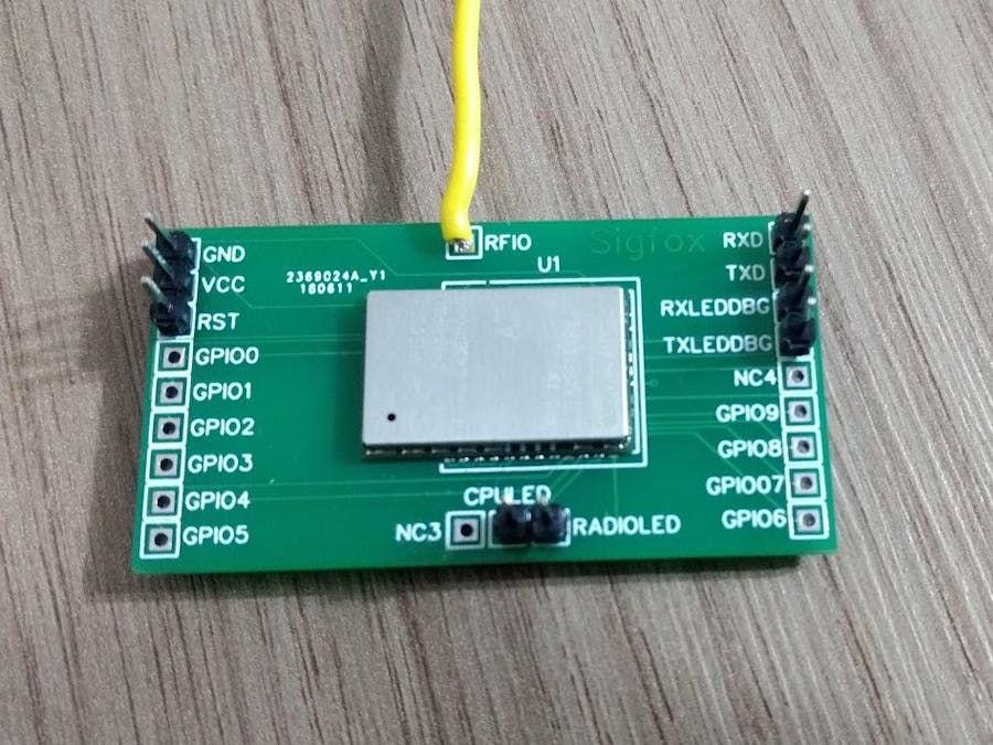
The objective of this project is to assemble a PCB board that can use a Sigfox modem from Wisol company. Sigfox is an LPWAN (Low power wide area network) design for IoT solutions, many companies assembly modem to talk with this network, but the development kits are expensive. Because of that, we design an open source PCB to soldering the Wisol Sigfox modem, and we did an end-to-end to test if it was working correctly.
Wisol Sigfox ModemThis is the Wisol Sigfox modem WSSFM10R2AT that is used in Brazil to access the network. The cost of this component is about R$ 26 reais, that is not expensive, but they use SMD connection, make impossible for human soldering this (I've tried!).
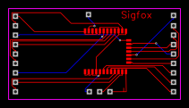
PCB Breakboard DesignThe PCB board was designed using the web software EasyEDA from JLCPCB, they have the component design for the Wisol modem WSSFM10R2AT, that make easy the process of PCB design. IMPORTANT: this board is not a shield or breadboard friendly, this just a PCB that make possible soldering the Wisol modem.
This layout could be download here: https://easyeda.com/walter.coan/sigfoxSFM10R2
Breakboard BuildThe next step, is to solder the modem on the PCB, to do that first we carfully put solder paste in all connections.
Then the Wisol Sigfox modem was place on the PCB.
Then the most challange process, the PCB was cooked into an eletric oven for 8 minutes at 220 celcius degree.
Before the PCB gets cold, we manually solder the header pins (VCC, GND, RST, RXD, TXD, CPULED and RADIOLED).
And this is the final breakboard!
The final step is test this board with a Raspberry Pi 3 model B, because the Wisol Sigfox modem works with 3.3v, and the Raspberry Pi is the best choice for this job. To connect the Raspberry Pi to the board we use this jumpers like this:
PCB Raspberry PiGND -> GND(pin 6)VCC -> 3.3v (pin 1)RXD -> GPIO14 (TXD pin 8)TXD -> GPIO15 (RXD pin10)
To use the CPULED and RADIOLED on PCB just each one to a jumper and connect to an LED and the other LED terminal to GND.
IMPORTANT: in the PCB we just connect a wire in the RFIO port to work like an antenna, but we strongly recommend to use a professional antenna.
The next step is to connect to the Wisol Sigfox modem using the serial port into the Raspberry Pi (/dev/ttyAMA0). For this task we install the software minicom, and use this command to connect:
minicom -b 9600 -D /dev/ttyAMA0
Then you have to configure the local echo, to see the serial AT commands you are typing. To do that just press CTRL-A Z E
To check if this step works, just type AT <enter>, the modem will respond with an OK.
The next step is to registry your Wisol Sigfox modem into the Sigfox network. To do that you have to create a developer account into the website https://backend.sigfox.com
The Wisol Sigfox modem registration needs two information from the device the: Device ID and PAC. To get this information just type in the minicom session:
AT$I=10
AT$I=11
The Wisol Sigfox modem will response this two hex numbers, go to Sigfox backend site, and click in Devices and new option:
Select your group.
Inform the ID, name (could be anything) and the PAC number, then click the link to find the End product certificate, and select the option "Register as a prototype (remaining prototypes which can be registered in your group: 999)". And select the device Type (you should create the type before do this, sorry) Confirm with the OK button.
Then to check if your device is working, go back to the devices page, and click the link in the ID column.
You should see all the details about your device, then click on messages link, this screen is important to debug and see all the messages did you receive. Stay on this page and go back to the raspberry pi terminal.
Type this two commands,
AT$RC
AT$SB=1
The command AT$SB=1 will send the bit 1 to the Sigfox network. The command AT$RC is now detail in Wisol AT manual, but I found this trick in one forum, and works for me!
If you go back to the Sigfox page, you probably will see that the message arrived the Sigfox server!
Now we can send this messages to Azure IoT Hub, to do that we need to configure an callback service that will be call from Sigfox when a new message comes. Go back to the device type, and select your device type.
Then on the device type page, select the option callbacks.
Then select Microsoft Azure IoT hub.
In this page you do all the callback service configuration:
- Type: select UPLINK the communication works in one direction device to server
- Custom payload config: its an option to process the message from the device, using this str::char:5, i'm converting the messages from the device to a string with five letters (this is optional)
- Connection string: this is your connection string from Azure IoT Hub. The string must be from the owner account:
- JSON body: the last is to format the message that will be send to IoT Hub, using this variables.
When you finish you will see that the callback service will be registry, this column errors show the last error detail the Sigfox has to call Azure IoT Hub.
Going back to the raspberry pi terminal, use this two commands to send a data frame in hex to the Sigfox service. This value is the string "AZURE" in hex.
AT$RC
AT$SF=617a757265
If you connect with the Device Explorer app, to monitor your new device, you will see the messages from they.


Comments
Please log in or sign up to comment.