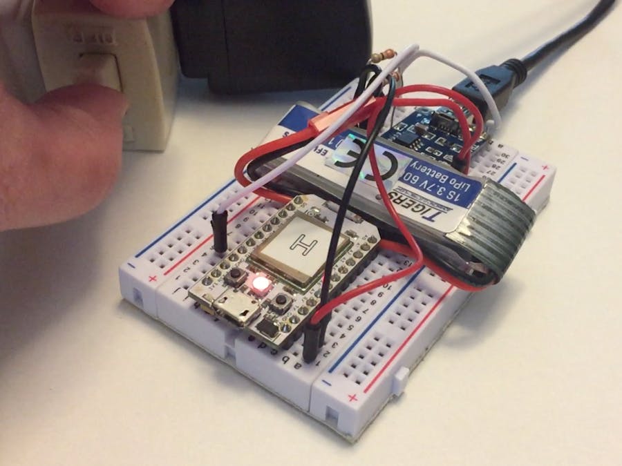
I was having problems with a particular circuit in my home randomly tripping the breaker. Normally this would be no problem if it wasn't the circuit that my garage door and extra refrigerator are on. Since the garage isn't a place my family normally hangs out, the refrigerator could go for hours without power. Fortunately, the refrigerator kept its cool and no food was spoiled, but I didn't want to chance it!
A power monitor was needed that could send me alerts whenever power to that particular circuit was lost. This way I could A) reset the breaker to restore power and, B) track exactly when power was lost so I could try to establish a trend and troubleshoot the issue. In the end, this turned into a Schrödinger's power circuit -- if it wasn't monitored, we couldn't tell the status until it was observed. Once observed, the thing never lost power again! Rather than chance it, this device now has a permanent home in my garage (with some extra bells and whistles not discussed in this article).
BuildThe build is quite simple and can be done in a few minutes. Before getting started, you will want to make sure the battery has a full charge.
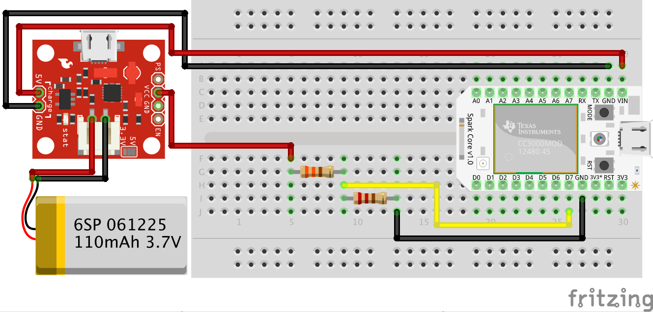
1. Place the microcontroller on a breadboard.
2. Hook up a jumper from the charger load/battery + pin to the microcontroller VIN.
3. Hook up a jumper from the charger load/battery - pin to the microcontroller GND.
4. Hook up a jumper from the charger USB+/VIN pin to an empty row in the breadboard. We'll call this USB+ for reference below.
5. Place the 330 Ohm resistor from the USB+ jumper to another empty row on the breadboard.
6. Place the 220 Ohm resistor from the open end of the 330 Ohm resistor to another empty row on the breadboard.
7. Hook up a jumper from the 220 Ohm resistor open end to GND on the microcontroller.
8. Hook up a jumper from the row where the 330 Ohm resistor and 220 Ohm resistor meet to an input pin on the microcontroller. I used D7 on the Spark Core since it has an LED attached and lights up if there is power (this also works for a Photon or even Electron).
9. Connect the battery to the LiPo/Li-Ion charger.
10. Power the charger from a USB wall wart and USB cable.
11. Flash the code to the microcontroller.
12. Unplug the USB power (either the USB cable or the wall wart) and watch the RGB LED turn red!
NotificationI used IFTTT to send the notifications to my cell phone and e-mail. E-mail is better for tracking a history to establish trends. You could also use something like a Google Spreadsheet. I didn't explore further options since I stopped losing power the moment I started monitoring it!
I have published an IFTTT recipe as an example of sending a notification to your smartphone when the power goes out or is restored.


Comments
Please log in or sign up to comment.