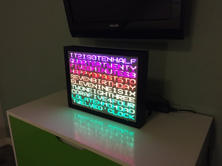
I've always been enamored with word clocks since I saw one a year or so ago. Once I realized that I could make one "easily" with my wife's Silhouette Cameo and a big vinyl sticker, I decided to go for it. I also wanted to have something with lots of NeoPixels to show off at Maker Faire!
Build Instructions
Please, please, PLEASE read through these instructions before you even fire up your cutting software. I pretty much put this project together from the hip without a whole lot of reasonable planning. I was also in a time crunch to finish this before going to display it at Maker Faire. Depending on time and distractions, this project could take 1-2 weeks to complete.
The Lettering
1. Design the stencil using whatever design software works with your vinyl cutter. Try to find a fixed-width (or monospaced) font that you like. Make sure you leave some space on the outer edges for your microcontroller. Be sure to mirror it before you're finished.
2. Use the vinyl cutter to cut out the vinyl.
3. Transfer the vinyl to the glass on the inside of the shadow box (this is why you needed to mirror it). I would recommend spraying the glass with some soapy water to make it easier to move the vinyl around on the glass to get it just right.
The Foamboard
1. Once everything has dried, get out the black foamboard and your favorite cutting tools. You'll want to cut strips about 1" tall and 16" in length (if you have a 12" x 16" frame). The number of strips you'll need is the number of rows of characters plus one.
2. Start positioning the long strips in the shadow box between rows. Use hot glue to anchor them on the left and right sides. The strips may not be perfectly straight, but you're about to fix that.
3. Start cutting more 1" strips but make them 12" in length. The number of strips you'll need is the number of columns of characters plus one.
4. Here comes some tedium! One at a time, lay the 12" strips over the 16" strips and mark where you'll need to cut. Yes, you'll be cutting lots of small squares. They don't have to be perfect since you can't really see them in the finished product. Place those small squares one column and row at a time. These little squares will also help straighten out any curved rows of the 16" strips.
5. Every so often, you'll want to hot glue some of the squares to the rows. You may need to make adjustments as you go, so use the glue sparingly for now.
6. Once all the small squares are in place and everything is lined up, do a triple check that you can see all the letters through the glass without any blockages.
7. If everything checks out, start glueing the small squares to the rows. I just put a small dab of glue in each corner in the back of the frame, and it seemed to hold up pretty well.
8. If things are a little loose on the outer edges, cut some more foamboard to make sure everything fits securely.
Soldering
1. Time to start soldering... a lot! Operating one row at a time, use the hook-up wires and strippers to solder each "pixel" together. + goes to +, - goes to -, and data (usually the middle pin) to data. The LEDs I purchased had arrows. You'll probably want to test all the connects every 3-5 pixels or so.
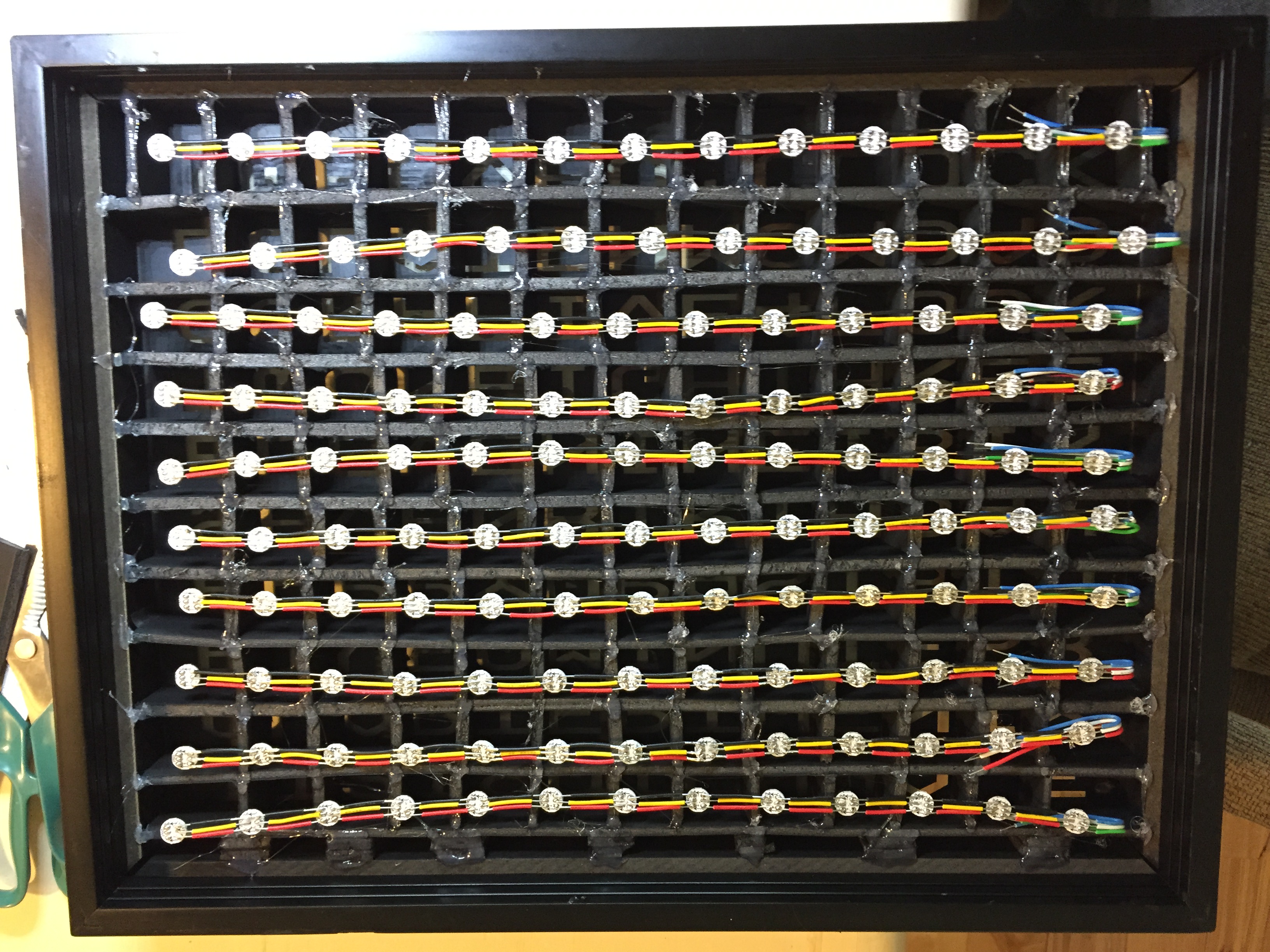
2. Once you've soldered your rows, lay the soldered rows over the foamboard in the back of the shadow box. Be sure to face the LEDs towards the glass. I oriented the data direction of each row to snake up the display. This is optional, but it will save you a lot of hook-up wire.
3. You may need to make some more adjustments to the foamboard, so triple check everything again.
4. Now start glueing the soldered pixels to the foamboard where the wires cross over the little squares. You may want to skip 2 or 3 pixels between glue joints, but make sure you do the outermost left and right pixels as anchors. If you glue all of the pixels, I promise that you will have to pry the glue off later to debug. Less glue makes this a lot easier!
5. After the rows have been glued down, use some longer hook-up wires to connect the 5V, data, and ground on all the rows, snaking your way up the display. Since there is some attenuation, at least on the 5V, you may want to not connect the 5V and ground pins at some point around 50-75% of the way up.
6. If you left a break in the 5V and ground lines as mentioned above, use hook-up wire to run a long 5V and ground from your power source to the rows at the break.
The Electronics
1. Cut off the barrel connector on the power supply and strip and expose the red 5V and black ground wires.
2. Use some hook-up wire to "T" the connections to 5V and ground so that you can split power to a few different places.
3. Connect 5V to VIN on your microcontroller. Connect ground to ground on your microcontroller. Connect 5V and ground to the appropriate places at the start of your pixels and to any breaks. To keep things easy, I didn't use a breadboard for the microcontroller and simply used some female jumper wires directly to the headers on the microcontroller. That way you can take it out if the need arises.
4. (Optional) If you decided to use a sensor like the DHT22, go ahead and hook it up to the microcontroller. Be sure to draw your the power for the sensor from a 3v3 pin.
5. Finally, cram the microcontroller (and optional sensor) into one of the edge sections of your frame. If you choose a corner, it will make it easier to run the power into the frame.
Final Assembly
Last, but not least, affix some of the tracing paper to the front of the display box. This will help diffuse the light coming from the LEDs. The downside to putting the tracing paper on the outside is that you only see the lit letters. It looks good this way, but I also plan on trying it out on the inside of the glass in my next word clock project (currently waiting on the LEDs to arrive).
Troubleshooting
There's not much I can recommend here other than having some alligator clips, a multimeter, and a hot soldering iron ready. Loose solder joints will most likely be the problem. The LED pads can be weak as well, so watch out for that.
The Code
Coming soon! I'm still cleaning it up. I'm also writing a little web app that you can run from your smartphone to change various settings.
Follow-Up
If you have any questions, concerns, or need help, consider joining and posting in the Particle forums. My free time with 2 young kids is pretty erratic, so I may not be able to answer questions directly or timely!


Comments
Please log in or sign up to comment.