The ESP8266 is a great platform for building myriads of IoT devices. One of its shortcomings however is the lack of multiple Analog-to-Digital Converters (ADC's). I circumvented this issue by adding the Texas Instruments ADS1115 to the I2C bus and gaining 2 differential ADC's. This setup was used to build an Energy Monitor described in a separate project. This project deals with bring the Energy Monitor to the Blynk platform.
The challenge when building an application specific daughterboard in the embedded electronics arena is always to support a range of motherboards when no standards exist for the ESP8266 (unlike the Arduino Shields system). I initially designed my energy monitor for the Adafruit Feather series with a Grove connector for the I2C bus to be compatible with any other platform supporting this bus.
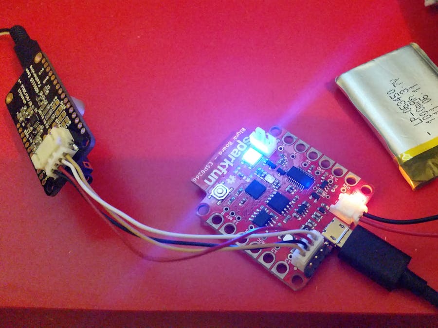
The Sparkfun Blynk board is built for experimentation with the large crocodile clip friendly connectors and a JST header for the I2C bus. I also soldered the headers next to the JST connector, which match the Grove layout exactly. Not sure if this is coincidence or design feature.
Then I hooked up the Energy Monitor Featherwing and loaded an I2CScanner sketch onto the Blynk board via the Arduino IDE( targeted to the Sparkfun Thing Dev board) to make sure it was detected.
Once the ADC was tested to be working, I proceeded to modify the Sparkfun example firmware for detecting if the Washing Machine has finished its cycle to report Energy readings instead.
The first step was to get the board connected to the Blynk Cloud Server. I installed the Blynk app from the appstore, generated a key and entered this together with my wifi details into the template sketch.
Once wifi and blynk server connection was working I copied over the energy measurement code from my NodeMCU and Adafruit Feather based code into the Blynk sketch. The previous code required me to handcraft POST requests to send data to the cloud service. Blynk libraries make it much easier using the "VirtualWrite" method and concept for virtual pins for variable storage.
I scanned in the Sparkfun provides QR for some Energy Points and built a basic dashboard in minutes to display a time series and instantenous voltage, current, power and power factor.
Then I hooked up a bulb, a potential transformer and current transformer to capture data and calibrate the system. This is when the potential of Blynk as a bi-directional system comes into play. Previously I had to calibrate the system by trial and error. Afterwards I hard coded voltage and current multiplier values into the ESP8266 sketch. This also meant that if I switched to a different transformer or current clamp, new firmware had to be loaded. With the Blynk option, I can capture calibration constants via sliders and persist them on eeprom after loading the initial sketch. This option make deployment and calibration really easy for the energy monitor users.
The calibration procedure is essentially one of choosing multipliers where the monitor returns known real world values. My test load is a 110W lamp. I first adjust the voltage multiplier until 240V nominal is measured on average, then I tweak the current multiplier to get the required real power of 110W. Then I adjust the phase shift factor to obtain power factor of 1.00 for this purely resistive load. At this point the Energy monitor is caibrated at this data point and scales up to a 10kW fairly linearly.
Final TouchesTo remove hardcoded wifi access point name/password and Blynk key from the public sketch I took advantage of the captive portal based configuration tool - WifiManager. This setup throws up a setup page on first run to capture wifi details and Blynk key. I also mae a custom JST PH 4-pin cable to neaten up the connection to the monitor board.


_3u05Tpwasz.png?auto=compress%2Cformat&w=40&h=40&fit=fillmax&bg=fff&dpr=2)


Comments
Please log in or sign up to comment.