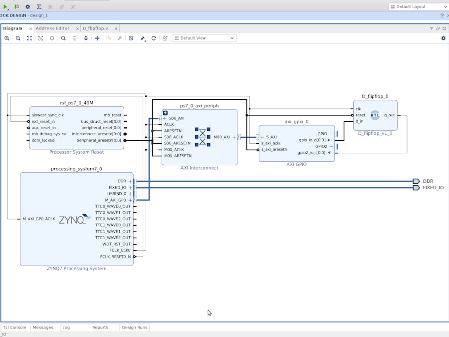
One of the challenging aspects I've found to using the Vivado IDE is how to get my custom RTL files to interact seamlessly with the logic/IP blocks I've laid out in the project's block design. While I have used an AXI GPIO configuration with custom HDL wrapper in the past to accomplish this, I recently discovered the Add Module option in the block design. This option simply tells Vivado to look for all valid RTL modules and let the user select which one to import into the block design with the IO ports mirroring how they are coded in the RTL file.
I'm filing this away as something I wish I had discovered a long time ago, and it's almost embarrassing that I recently discovered this. But it just goes to show you that no matter how much of an "expert" you become, there is always something new to learn.
I'm currently using Vivado 2019.2, but as far as I'm aware this feature is available is pretty much all of Vivado's releases (feel free to correct me in the comments below if this is incorrect).
Create Vivado ProjectTo start this example, I created a new Vivado project based on the Zynqberry (this is just my example, but the content of this project is not specific to any particular FPGA development board).
Add Design File & Write Custom RTLAny custom RTL that's not for simulation purposes (ie a testbench) are considered a design source in Vivado. Do add the empty file to write RTL in (in Verilog based on my project settings), use the Add Sources option from the Flow Navigator and select Add or create design sources then click Next.
The next window allows for existing RTL files to be added with the Add Files option or to create a new blank file with the Create File option.
In this case, I created a new file titled D_flipflop and added the following logic:
module D_flipflop(
    input clk,
    input reset,
    input d_in,
    output reg q_out
    );

    always @ (posedge clk)
        begin
            if (reset == 1'b1)
                begin
                    q_out <= 1'b0;
                end
            else
                begin
                    q_out <= d_in;
                end
        end
endmoduleUsing the Create Block Design option in the Flow Navigator window, add a new block design to the project.
Add the Zynq processing system IP block to the design and run the Block Automation that appears to apply the board presets and other basic/bare bones settings to it.
Add the RTL Module to the Block DesignTo add the RTL module of the D flip-flop that we created in the previous step, right-click anywhere in the blank space of the Diagram window and select the Add Module... option.
Vivado will automatically show all of the valid RTL modules it finds in the current project. Since the only module that's been written or imported into the current project is our D flip-flop, it's the only option in this instance.
To give the flip-flop a source/sink, I added an AXI GPIO IP block with the first channel as a single-bit output and the second channel as a single-bit input. When the connection automation appeared, I only chose to run it for the AXI interface of the GPIO since my custom module didn't appear as an option for the connection automation for the GPIO and GPIO2 ports.
After running the connection automation for the AXI GPIO block, I connected the output GPIO channel to the d_in of the flip-flop and the q_out of the flip-flop to the input GPIO channel.
After getting it all connected, the design successfully passed validation with one minor warning about ensuring the clock property was synced with the custom RTL module, but this warning can be safely ignored.
With the block design complete, a HDL wrapper can be generated for the design and left to Vivado to auto-manage:
Once the HDL wrapper is created for the block design, you'll see the Verilog file of the flip-flop pulled into the hierarchy as an IP under the block design (design_1.bd).
And that's it, the rest of the project flow is business as usual from here! I'm excited to start using this method in my future designs.


Comments
Please log in or sign up to comment.