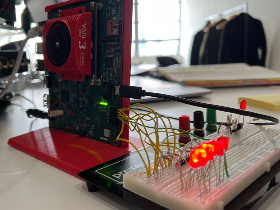
With so much focus on hardware acceleration, machine learning, and AI applications in the FPGA world as of late, I've been using my Kria KV260 quite a bit. Mostly I've been utilizing the USB, MIPI, Ethernet, and DisplayPort connectors but realized I haven't used the PMOD connector as of yet.
While planning my next project with the Kria, I realized I needed some simple I/O that the PMOD would be ideal for. This is also when I realized there wasn't a ton of documentation on using the PMOD on the Kria KV260 so I figured a quick little project on just that would be beneficial.
HLS C codeTo control the PMOD IO on the Kria KV260 board, I decided a simple bit manipulation C++ application written in HLS and exported as an IP to use in the Vivado block diagram would be a good option to make the PMOD IP accessible to a Jupyter Notebook in Pynq running on Ubuntu on the Kria.
The application is a simple function that either sets the specified PMOD I/O pin high/low or it applies a user-specified number as a bit mask to all 8 I/O PMOD pins, then it returns the bit mask of the 8 PMOD I/O pins current status.
C++ bit manipulation code:
#include <stdio.h>
#include <unistd.h>
#include <stdint.h>
#include <stdbool.h>

typedef unsigned short int u16;

u16 pmod_io(u16 io_ctrl, u16 io_num, u16& pmod) {
	#pragma HLS INTERFACE ap_ctrl_none port=return
	#pragma HLS INTERFACE s_axilite port=io_ctrl
	#pragma HLS INTERFACE s_axilite port=io_num
	#pragma HLS INTERFACE s_axilite port=pmod

	u16 pmod_mask;

	if (io_ctrl == 0xf){
		pmod_mask = 0;
	} else if (io_ctrl == 0xa) {
		pmod_mask = (1 << io_num);
	} else if (io_ctrl == 0x5) {
		pmod_mask = (0 << io_num);
	} else if (io_ctrl == 0x1) {
		pmod_mask = io_num;
	} else {
		pmod_mask = pmod_mask;
	}

	pmod = pmod_mask;

	return pmod_mask;
}
Run C synthesis and export the IP from HLS (see full process in my previous post here if you're unfamiliar with HLS), then add the IP to the Vivado project IP repository. I'm using the Vivado project I created for the Kria KV260 in v2021.2 (see setup here - same as 2021.1).
Add the PMOD IP to the block design in Vivado and run the resultant connection automation to connect the AXI interface.
Since only the lower 8 bits of the 16-bit output from the HLS IP is being used, add a Slice IP block and configure it for the lower 8 bits:
Resulting in the following block design:
Validate the block design and save it, then create or regenerate the HDL wrapper by right-clicking on the block design file in the sources tab and selecting Create HDL Wrapper... and leaving the default option to allow Vivado to auto-manage it (same as usual).
With the PMOD pins now available in the block design and made external to the design with the top level HDL wrapper, create a new constraints file (Flow Navigator > Add Sources > Add or create constraints) and copy the following constraints for the PMOD connector into it:
set_property PACKAGE_PIN H12 [get_ports pmod[0]] ;# PMOD pin 1 - som240_1_a17
set_property PACKAGE_PIN B10 [get_ports pmod[1]] ;# PMOD pin 2 - som240_1_b20
set_property PACKAGE_PIN E10 [get_ports pmod[2]] ;# PMOD pin 3 - som240_1_d20
set_property PACKAGE_PIN E12 [get_ports pmod[3]] ;# PMOD pin 4 - som240_1_b21
set_property PACKAGE_PIN D10 [get_ports pmod[4]] ;# PMOD pin 5 - som240_1_d21
set_property PACKAGE_PIN D11 [get_ports pmod[5]] ;# PMOD pin 6 - som240_1_b22
set_property PACKAGE_PIN C11 [get_ports pmod[6]] ;# PMOD pin 7 - som240_1_d22
set_property PACKAGE_PIN B11 [get_ports pmod[7]] ;# PMOD pin 8 - som240_1_c22

set_property IOSTANDARD LVCMOS33 [get_ports pmod*];
set_property SLEW SLOW [get_ports pmod*];
set_property DRIVE 4 [get_ports pmod*];Run synthesis, implementation, and generate a bitstream for the new design. After the bitstream has been generated, reopen the block design to export the block design TCL file and bitstream file (File > Export > Export Block Design... and Export Bitstream File...). Be sure to name each file the same (requirement for using the Overlay library in Pynq).
Also grab a copy of the hardware hand-off file from /<Vivado project directory>/<Vivado project>.gen/sources_1/bd/<bd name>/hw_handoff/<bd_name>.hwh and rename it to match the block design TCL and bitstream files. Then upload the three files to a new folder in Jupyter on the Kria (connect the Kria to your local network and open http://kria:9090/ in a web browser from host PC.
Once the files are uploaded, create new notebook:
Load the overlay bitstream to configure the programmable logic on the Kria with the bitstream containing the PMOD HLS IP:
from pynq import Overlay
overlay = Overlay('/home/root/jupyter_notebooks/kv260_pmod/kv260_pmod.bit')
overlay?
The write a simple function to easily pass the control parameters to the IP and read back the PMOD bit mask via the AXI interface:
from pynq import DefaultIP

class PmodDriver(DefaultIP):
    def __init__(self, description):
        super().__init__(description=description)

    bindto = ['Knitronics:PMOD:pmod_io:1.0']

    def pmod_io_func(self, io_ctrl, io_num):
        self.write(0x10, io_ctrl)
        self.write(0x18, io_num)
        return self.read(0x20)
Look up the VLNV reference designator for the PMOD HLS IP in Vivado block diagram to bind the Python driver to.
And lookup the AXI register offset values in the C synthesis report in HLS.
Then reload the overlay so it can utilize the function written in the previous step:
from pynq import Overlay
overlay = Overlay('/home/root/jupyter_notebooks/kv260_pmod/kv260_pmod.bit')
overlay?
Test out the the PMOD IP functionality. I passed a bitmask to set PMOD I/O pins 1 and 6 high:
overlay.pmod_io_0.pmod_io_func(0x1,0x42)For a byte with bits 1 and 6 set high, this binary value equates to the decimal value 66, which is returned by the Python function. And since I have an LED connected to the PMOD header on the KV260 I also see LEDs on pin 1 and 6 illuminate.
(Forgive me, my LEDs aren't in sequential order from pin 1 to pin 8 so pins 1 and 6 are on opposite ends).


Comments
Please log in or sign up to comment.