In this Meadow project we're going to learn how to use a distance sensor, rotating it with a SG90 Micro servo, and show detected obstacles in a ST7789 as a Radar graphic interface. All these peripherals will be controlled using Meadow.Foundation.
Meadow.Foundationa platform for quickly and easily building connected things using.NET on Meadow. Created by Wilderness Labs, it's completely open source and maintained by the Wilderness Labs community.
If you're new working with Meadow, I suggest you go to the Getting Started w/ Meadow by Controlling the Onboard RGB LEDproject to properly set up your development environment.
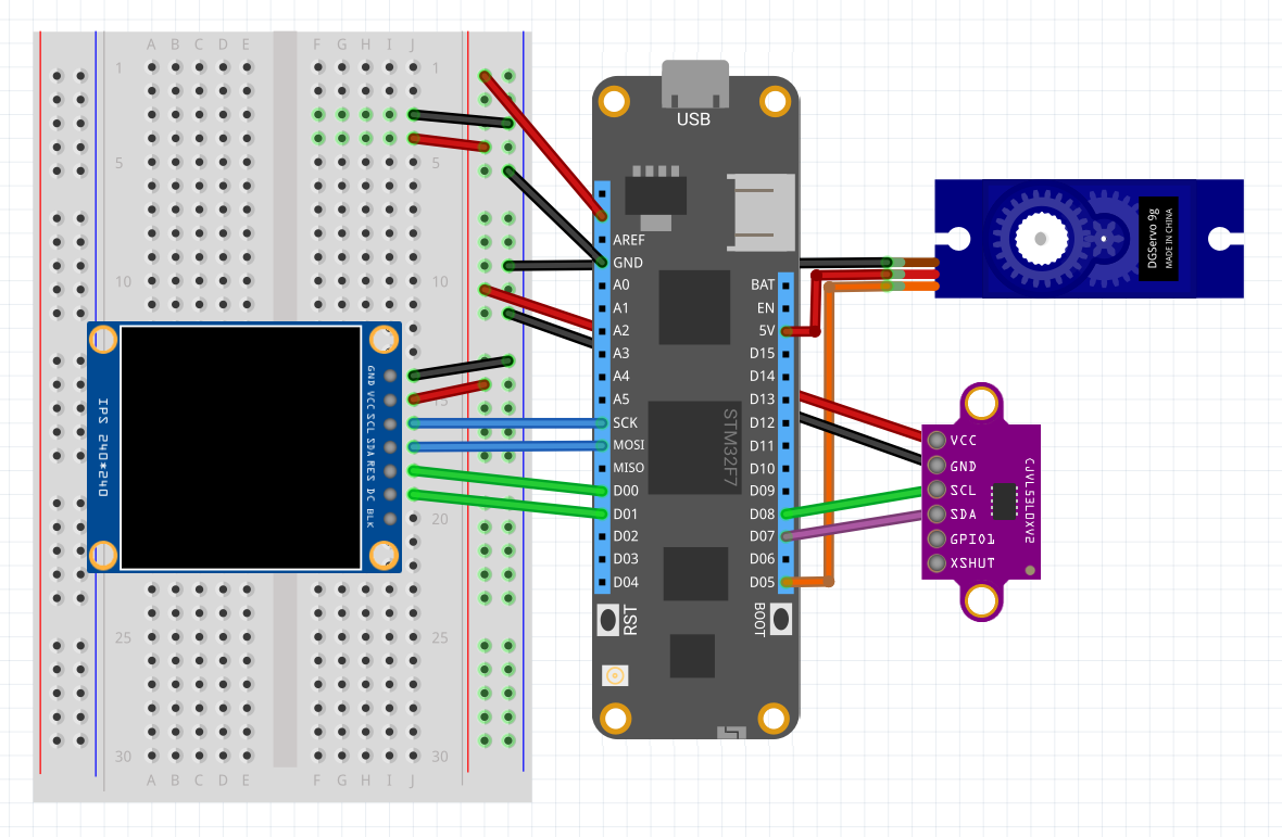
Step 1 - Assemble the projectWire your project like this:
If you have a 3D printer, you can download this STL file (in the attachments section) and print this object to place the Servo to hold it upright next to your prototype board.
You can also print this small custom part to hold the distance sensor, and you can use a couple of screws top to mount it on a servo top. Use M2 screws and bolds to put it together like the photo below. Notice we're putting a nut between the PCB and the part so the circuit is not in contact with the PLA material.
Create a new Meadow Application project in Visual Studio 2019 for Windows or macOS and name it ObstacleRadar.
Step 3 - Add the required NuGet packagesFor this project, search and install the following NuGet packages to your project:
Step 4 - Write the code for ObstacleRadarCopy the following code below:
public class MeadowApp : App<F7Micro, MeadowApp>
{
    GraphicsLibrary graphics;
    St7789 display;
    Vl53l0x sensor;
    Servo servo;

    float[] radarData = new float[181];

    public MeadowApp()
    {
        Initialize();

        Draw();
    }

    void Initialize()
    {
        var led = new RgbLed(
            Device,
            Device.Pins.OnboardLedRed,
            Device.Pins.OnboardLedGreen,
            Device.Pins.OnboardLedBlue);
        led.SetColor(RgbLed.Colors.Red);

        var config = new SpiClockConfiguration(
            24000, SpiClockConfiguration.Mode.Mode3);
        var spiBus = Device.CreateSpiBus(
            Device.Pins.SCK,
            Device.Pins.MOSI,
            Device.Pins.MISO, config);

        display = new St7789(device: Device, spiBus: spiBus,
            chipSelectPin: Device.Pins.D02,
            dcPin: Device.Pins.D01,
            resetPin: Device.Pins.D00,
            width: 240, height: 240);

        graphics = new GraphicsLibrary(display);
        graphics.CurrentFont = new Font12x20();
        graphics.Rotation = GraphicsLibrary.RotationType._270Degrees;

        var i2cBus = Device.CreateI2cBus(I2cBusSpeed.FastPlus);
        sensor = new Vl53l0x(Device, i2cBus);
        sensor.StartUpdating(200);

        servo = new Servo(
            Device.CreatePwmPort(Device.Pins.D05), NamedServoConfigs.SG90);
        servo.RotateTo(0);

        led.SetColor(RgbLed.Colors.Green);
    }

    void Draw()
    {
        int angle = 160;
        int increment = 4;
        int x, y = 0;

        while (true)
        {
            graphics.Clear();

            DrawRadar();

            graphics.DrawLine(120, 170, 105,
                (float)(angle * Math.PI / 180), Color.Yellow);

            if (angle >= 180) { increment = -4; }
            if (angle <= 0) { increment = 4; }

            angle += increment;
            //servo.RotateTo(angle);

            graphics.DrawText(0, 0, $"{180 - angle}°", Color.Yellow);

            if (sensor?.Conditions?.Distance != null &&
                sensor?.Conditions?.Distance.Value >= 0)
            {
                graphics.DrawText(170, 0,
                    $"{sensor.Conditions.Distance.Value}mm", Color.Yellow);
                radarData[angle] = sensor.Conditions.Distance.Value / 2;
            }
            else
            {
                radarData[angle] = 0;
            }

            for (int i = 0; i < 180; i++)
            {
                x = 120 + (int)(radarData[i] * MathF.Cos(i * MathF.PI / 180f));
                y = 170 - (int)(radarData[i] * MathF.Sin(i * MathF.PI / 180f));
                graphics.DrawCircle(x, y, 2, Color.Yellow, true);
            }

            graphics.Show();
            Thread.Sleep(100);
        }
    }

    void DrawRadar()
    {
        int xCenter = 120;
        int yCenter = 170;

        var radarColor = Color.LawnGreen;

        for (int i = 1; i < 5; i++)
        {
            graphics.DrawCircleQuadrant(xCenter, yCenter, 25 * i, 0, radarColor);
            graphics.DrawCircleQuadrant(xCenter, yCenter, 25 * i, 1, radarColor);
        }

        for (int i = 0; i < 7; i++)
        {
            graphics.DrawLine(xCenter, yCenter, 105,
                (float)(i * Math.PI / 6), radarColor);
        }
    }
}
Lets breakdown the explanation by methods:
Initialize
First thing we initialize is an RgbLed object which we immediately set the LED to Red to indicate the app has started. Next we initialize the ST7789 display and the graphics library, passing the display object (you can learn more about displays and graphics here). Also we instantiate the distance sensor (Vl53l0x) and the Servo with the named servo configuration SG90. Finally, we set the LED to green to indicate the initialization process has completed successfully.
DrawRadar
This method will draw the radar interface to the display using the graphic library DrawCircleQuadrant and DrawLine methods.
Draw
This method is an infinite loop where it first calls DrawRadar to draw the radar graphics to the display, activates the distance sensor to check for obstacles, and rotates the servo back and forth by 4 degrees in a 180 degree range. The current degree will be shown in the top left corner of the screen.
If the distance sensor detects and obstacle, it will draw the text of the distance measured in the top right corner of the screen and will draw a yellow dot in the radar according to the distance detected.
Step 5 - Run the projectClick the Run button in Visual Studio. It should look like to the following GIF:
This project is only the tip of the iceberg in terms of the extensive exciting things you can do with Meadow.Foundation.
- It comes with a huge peripheral driver library with drivers for the most common sensors and peripherals.
- The peripheral drivers encapsulate the core logic and expose a simple, clean, modern API.
- This project is backed by a growing community that is constantly working on building cool connected things and are always excited to help new-comers and discuss new projects.


Comments
Please log in or sign up to comment.