


Hardware components | ||||||
 |
| × | 1 | |||
 |
| × | 1 | |||
| × | 48 | ||||
| × | 47 | ||||
| × | 16 | ||||
| × | 1 | ||||
| × | 1 | ||||
| × | 1 | ||||
| × | 1 | ||||
| × | 1 | ||||
Software apps and online services | ||||||
 |
| |||||
Hand tools and fabrication machines | ||||||
| ||||||
 |
| |||||
| ||||||
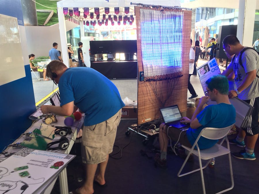
As demonstrated at Maker Faires around the world, it's the Windows Remote Wiring Powered LED Curtain!
The LED Curtain works in two parts. First, a Windows Phone 10 is used to take and process a picture for display. An Arduino™ (or Genuino™) is used to drive strips of LEDs to display the picture on the curtain. The phone communicates with the Arduino using Windows Remote Arduino over a Bluetooth™ connection.
This project highlights the potential of distributed computing for IoT projects. The LED curtain is composed of a 48 by 48 matrix of LEDs. For each LED, and RGB color value is specified. Each of red, green, and blue take one byte to store a value between 0 and 255. The memory needed to store a single picture comes out to 48 x 48 x 3 = 6912 bytes, quite a bit more than the SRAM available on Arduino Uno or Leonardo boards that we wanted to use for the project.
The solution was to offload the picture processing to the phone, and have it convert a picture into a list of color values for each LED. The phone can then transmit those values to the Arduino, and the Arduino can set the LEDs and dispose of the value, greatly reducing its memory requirement. Windows Remote Arduino, combined with a custom sketch of Standard Firmata, provide for easy communication between the two devices.
This post will walk you through how we constructed the curtain and wrote some of the code. The Bill Of Materials is listed and the source code is on Github, so you can follow along and build your own as well!
First time hearing about Windows Remote Arduino? Check out the Hackster post! (https://microsoft.hackster.io/en-US/windowsiot/basic-windows-remote-arduino)
Looking for more information about Firmata? Take a look at the source code over on Github! (https://github.com/firmata/arduino)
This project involves modifying power supplies and drawing a fair amount of current. You will need to ensure that any outlets, power strips, and breakers you use are rated to handle the power that will be drawn through them.
The power adapters used in this project have a peak draw of 2 Amps each at 100-240V. With 16 power adapters, that means you can end up drawing 32 Amps as peak draw. While you'll be able to condense the 16 power supplies down in to 2-3 surge protectors, you'll need to be careful about how you plug those into a wall outlet for power, or you'll end up tripping a breaker, blowing a fuse, or worse.
Start by assembling the power supply connectors. You’ll need to prepare all of the barrel connector to wire converter pieces, but doing so first helps speed up the next step. If you’re building to the frame as designed by the bill of materials, you’ll want to have a few feet of cable from the ends of the wires to the power brick. We left around eight feet to have plenty of spare cable to work with, but 4-6 feet (1.5m to 2m) would adequately stretch from the bottom of the curtain to the floor.
Next, lay out the bamboo curtain and position the LED strips on top of it. You'll want to leave some space on the left side of the curtain for the Arduino to be attached, and the strips should run top to bottom on the curtain. The left most strip needs to have the arrows pointing upward, the second left strip with the arrows downward, the third with the arrows up, and so on, alternating for all 48 strips.
Once you have the strips arranged, lay out the 4-pin connectors to plan out where each plug and receptacle end needs to go. The bottom of the left most strip will connect to the Arduino, the top of the left most strip will connect to the top of the second left strip, the bottom on the second left strip to the bottom of the third left, top of the third to top of the fourth, and so on.
The back and forth snaking of connections is necessary due to how the Arduino addresses the LEDs on the strips. The Arduino doesn't actually see this project as a two dimensional matrix onto which it can display an image. Instead, the Arduino treats all of the LED strips as a single, long strip. As mentioned in the introduction, the phone handles the process of converting the picture to the needed RBG values, but it also handles ordering the list of values for the Arduino, so there is a direct mapping between the list of color values and the LED that each color value is associated with.
Before soldering can begin, you need to plan out the power distribution for each LED strip. Each power adapter can properly power a group of three strips. This means that between groupings of strips, you must not solder the 5v cable to the LED strip. So, you’ll want to take the appropriate wire on the connector between strip three and strip 4, separate it out, and cover it with an end cap or other appropriate covering. Consult with the data sheet for the LED strips for which position is the 5v line.
Do this for the wires on both sides of the connector, to prevent any accidents. Then, do the same for the 5v wire connector between strips six and seven, 9 and 10, 12 and 13, and so on. This will leave each grouping of three with a power line running between them, and each grouping with only ground, signal, and clock lines running between them.
Next, you’ll need to splice a power supply connection into the 5v and ground wires of each grouping of LED strips. This is most easily done with some wire splitters, and your choice of crimp connectors/screw connectors/solder connectors. You want to be sure that you use the correct wire of the connectors, and that you leave some cable to solder this newly connected wire on to the LED strip (so that the strip can actually be connected to ground and power).
Finally, solder the LED strips to the connector you planned out for them. On every third strip, you should only be soldering three wires, instead of four, since you shouldn’t be soldering the 5v power wire. Additionally, solder connections wire to the bottom connections of your far left strip for the Data and Clock lines. At the end of soldering, you should have 48 separate LED strips, 16 of which are connected (or have open connections available to connect to) the power adapter wires, and one of which has dangling Data and Clock lines for connecting to the Arduino.
We found it safest to secure the Arduino and the Bluetooth module inside a plastic project case. This keeps the Arduino protected while you move the curtain around, as well as easier to secure to the curtain. You may also wish to drill extra holes in the plastic board, to pass zip ties through later for securing the board to the curtain. Wire the Arduino to the Bluetooth module: a 5v power pin, a ground pin, the RX pin, and the TX pin from the Arduino connect to their respective pins on the module.
Now that you have the LED strips and power supplies prepared, once again arrange the LED strips on the curtain. Once you have them positioned, double check that all of the connectors can reach each other, and then begin attaching the LED strips to the curtain. A few zip ties, placed evenly along the length of the strip, are adequate to securely hold the strip on the curtain.
Once the strips are attached, secure the Arduino board and Bluetooth module to the curtain near the bottom left of LEDs. This can be done by screwing in to the slats, or by passing zip ties through the holes you drilled in the plastic board in the Arduino Prep section. Connect the data line from the LED strips to the MOSI pin on the ICSP header (pin 4, the middle one closest to the edge of the board). Connect the clock line from the LED strips to the SCK pin of the ICSP header (pin 3, middle one closest to the center of the board). Finally, connect the ground line from the LED strips to any one of the ground pins on the Arduino. Making sure the Arduino and the LED strips share a common ground is important, otherwise the quality of the serial signal will suffer.
Next, assemble the clothes rack. If you’re using the same clothes rack and curtain as in the BoM, you’ll probably find it easiest to adjust it to its tallest position. If there is a lot of space between the top of the LED strips and the top of the curtain, you may wish to bundle the spare curtain up and secure it with zip ties, to help raise the viewing level of the LED strips.
Then, attach the shower curtain hangers to the top of your curtain, and hang the curtain from the top of the clothes rack. Optionally, if there is a lot of empty curtain space hanging at the bottom of your LEDs, you may wish to bundle it up and secure it with zip ties.
Finally, connect the LED strip connectors to one another, connect the power supply barrel connectors to the power supply cable, and connect the power supplies to power.
Clone the LEDMatrix Github repository listed in the software section below. In the “Arduino” folder, you’ll find three sub folders, with Arduino sketches that can be used for different project configurations. The GitHub readme describes what each one is for. For this project, you’ll use the “LedCurtainFirmata” folder. This is a modified version of Standard Firmata (https://github.com/firmata/arduino/blob/master/examples/StandardFirmata/StandardFirmata.ino
In this project, the Arduino handles very little of the program’s logic. A 48x48 matrix of LEDs is simply too large for the Arduino to process pictures and determine how to color each LED to draw the picture. As you can see in the Sketch, the Arduino receives that information from the phone, which has plenty of processing power to handle the task.
To see just how the phone handles the task, go back in the root of the GitHub repo and open the “UWP” folder. Inside, you’ll find a “RemoteLedMatrix” Visual Studio solution file. That solution file is configured and ready to deploy to a phone running Windows Phone 10.
As listed in the software requirements for the project, you’ll need Visual Studio 2015. The Community Edition works great, is free, and can be found at this link here (https://go.microsoft.com/fwlink/?LinkId=691978)
The code for the project is pretty straightforward. It leverages the Remote Wiring to communicate with the Arduino, so the lower-level communication is handled for us. If you’re interested into a deeper dive of Remote Wiring, the source code is available on Github (https://github.com/ms-iot/remote-wiring).
The project code here needs to take a picture, scale the picture and convert it to a list of colors, and send that list of colors via to the Arduino using Firmata:
- The “MainPage.Xaml.Cs” file is where you’ll find the code that handles initializing the camera and taking a picture. This portion of the code also handles creating and changing connections to the Arduino.
- The “Hardware/Lpd8806Matrixcontains the logic to scale the picture to the size of the LED curtain, convert the pixels in the Bitmap to a list of Color values, adjust the order of the list to match the order of the pixels in the LED curtain, and adjust intensity of the colors to appear correctly on the LEDs.
- The “Helpers/FirmataExtensions.cs” file contains some functions that take the list of colors and pass each color to the Arduino via calls into Remote Wiring.
Conclusion
The LED Screen powered by Windows Remote Arduino is a complex project which demonstrates the power of hybrid solutions. A similar project could be completed with a smaller dedicated panel such as the Adafruit 64x32 LED Matrix (https://www.adafruit.com/products/2277) or 32x32 Matrix (https://adafruit.com/products/1484), the latter of which has code available in the GitHub repository for this project.


_3u05Tpwasz.png?auto=compress%2Cformat&w=40&h=40&fit=fillmax&bg=fff&dpr=2)
Comments
Please log in or sign up to comment.