


Hardware components | ||||||
 |
| × | 1 | |||
 |
| × | 1 | |||
 |
| × | 1 | |||
 |
| × | 1 | |||
 |
| × | 1 | |||
 |
| × | 4 | |||
| × | 1 | ||||
| × | 1 | ||||
| × | 1 | ||||
Software apps and online services | ||||||
 |
| |||||
It is part of assignment submitted to Deakin University, School of IT, Unit SIT210/730 - Embedded Systems Development.
Project OverviewBackgroundIn today's world, home security is a paramount concern. Traditional security systems often rely on basic alarm systems and physical barriers, which can be easily bypassed. With the advent of smart home technologies, it is possible to create more sophisticated and responsive security systems that integrate various sensors and automated responses.
Existing WorkTraditional security systems typically include motion detectors, door/window sensors, and basic alarm mechanisms. Modern systems have started to incorporate smart technology, allowing for remote monitoring and control through mobile apps. However, these systems often come with high costs and require professional installation and monitoring services.
Problem StatementThe primary problem addressed by this project is the need for an affordable, DIY, and comprehensive home security system that integrates multiple methods of system control (RFID, keypad, and speech recognition) and provides automated alerts and responses in case of potential break-ins.
Requirements· Multi-method System Activation: Ability to lock and deactivate the system using RFID, keypad, and speech recognition.
· Redundant Door/Window Sensors: Use of microswitches to detect faults and potential break-ins with redundancy to minimize false alarms.
· Motion Detection: Integration of a PIR motion sensor to detect unauthorized movement inside the house.
· Automated Alerts and Responses: System should send SMS and make a call to the owner, play a warning audio, and start recording video during a potential break-in.
· Bluetooth Communication: Use of Bluetooth for communication between Arduino and Raspberry Pi.
Design PrinciplesThe design principles guiding this project include:
· Redundancy: Ensuring fault tolerance by using redundant sensors.
· User-Friendly: Providing multiple methods for system activation and deactivation.
· Automated Responses: Automating the alert and response mechanism to ensure timely action without manual intervention.
· Scalability: Designing the system to be easily extendable with additional sensors and functionalities.
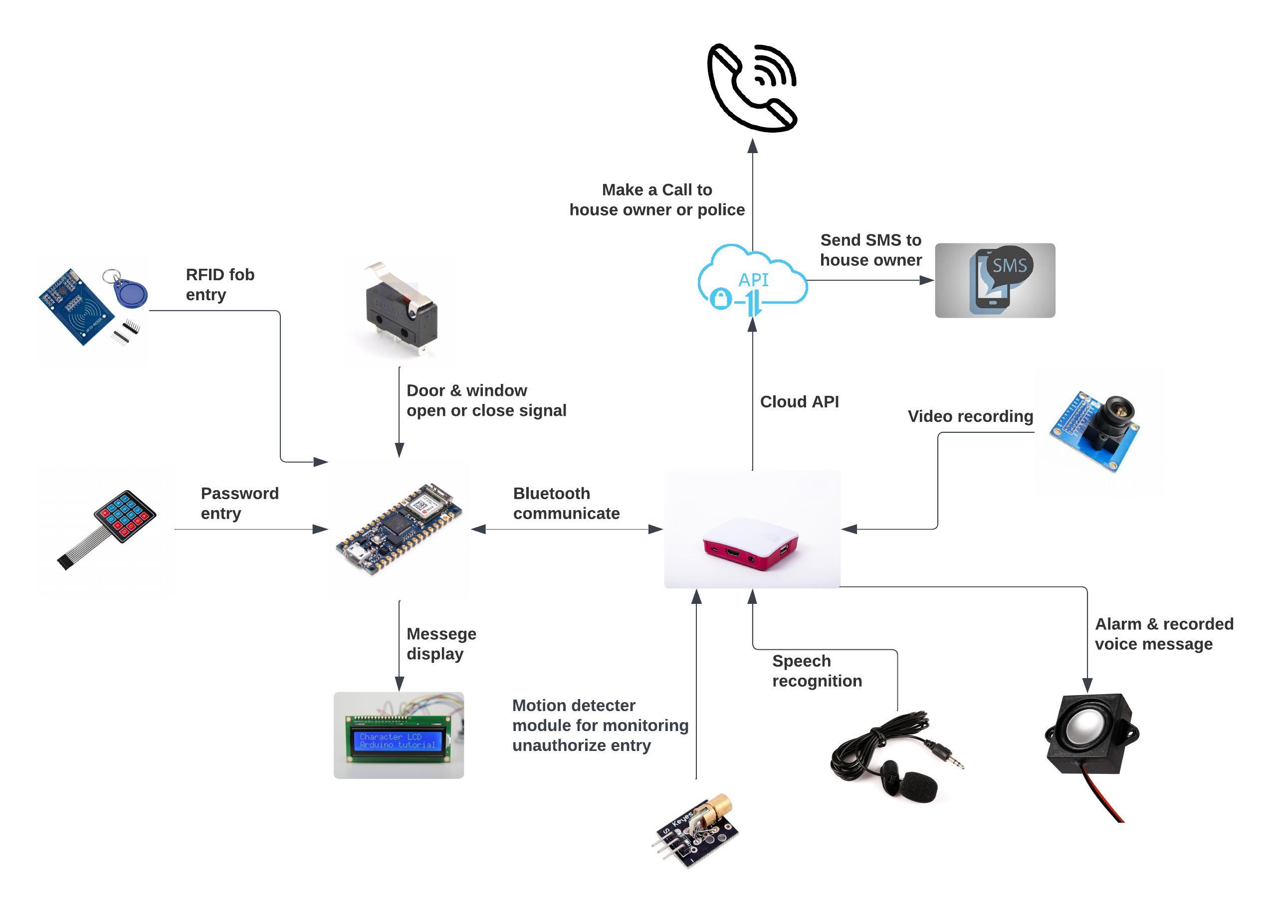
Prototype ArchitectureSystem Components· Arduino Nano 33 IoT: Handles RFID, keypad, microswitches, and Bluetooth communication.
· Raspberry Pi: Manages motion detection, camera recording, speech recognition, and Bluetooth communication.
· PIR Sensor: Detects motion inside the house.
· Microswitches: Monitor the status of doors and windows.
· LCD Display: Provides system status feedback.
· RFID Reader: Allows system activation and deactivation using RFID tags.
· Keypad: Provides an alternative method for system activation and deactivation.
· Camera: Records video during a potential break-in.
· Bluetooth Module: Facilitates communication between Arduino and Raspberry Pi.
Data Flow· System Activation/Deactivation: Users can activate or deactivate the system using RFID tags, keypad, or voice commands. The Arduino processes these inputs and updates the system state.
· Sensor Monitoring: The Arduino continuously monitors the microswitches for door/window status and sends updates to the Raspberry Pi via Bluetooth.
· Motion Detection: The Raspberry Pi monitors the PIR sensor. If motion is detected for more than 6 seconds and the system is locked, it triggers the alert mechanism.
· Alert Mechanism: Upon detecting a potential break-in, the Raspberry Pi sends an SMS and makes a call to the owner, plays a warning audio, and starts recording video.
· Feedback Loop: The system status is displayed on the LCD and logged in the serial monitor for debugging.
Link to Prototype Code on Githubhttps://github.com/Kenneth0120/Task11.1HDProject.git
Testing ApproachFunctional Testing· RFID: Tested with authorized and unauthorized tags.
· Keypad: Tested with correct and incorrect passwords.
· Speech Recognition: Tested with and without the wake word, and with correct and incorrect commands.
· Microswitches: Simulated door/window open and close events.
· Motion Sensor: Simulated motion and verified the response.
Integration Testing· Verified communication between Arduino and Raspberry Pi via Bluetooth.
· Tested the coordinated response to a potential break-in, ensuring all alerts and recordings were triggered correctly.
User ManualHardware SetupComponents Required:· Arduino Nano 33 IoT
· Raspberry Pi (latest version of Raspbian installed)
· RFID reader (MFRC522)
· Keypad
· PIR sensor
· Microswitches (for doors and windows)
· LCD display (LiquidCrystal_I2C)
· USB Microphone
· PiCamera (compatible with Raspberry Pi)
· Breadboards and connecting wires
Connecting Components:1. RFID Reader:
· Connect the RFID reader to the Arduino Nano 33 IoT using the SPI pins:
· SDA to pin 10
· SCK to pin 13
· MOSI to pin 11
· MISO to pin 12
· RST to pin 9
· GND and VCC to appropriate pins
2. Keypad:
· Connect the keypad to the Arduino:
· ROW0 to pin 8
· ROW1 to pin 7
· ROW2 to pin 6
· ROW3 to pin 5
· COL0 to pin 4
· COL1 to pin 3
· COL2 to pin
3. Microswitches:
· Connect the door and window microswitches to the analog pins on the Arduino:
· Door1 to pin A0
· Door2 to pin A1
· Window1 to pin A2
· Window2 to pin A3
4. LCD Display:
· Connect the LCD display to the Arduino via I2C:
· SDA to A4
· SCL to A5
· GND and VCC to appropriate pins
5. PIR Sensor:
· Connect the PIR sensor to the GPIO pin 18 on the Raspberry Pi.
6. USB Microphone:
· Plug the USB microphone into a USB port on the Raspberry Pi.
7. PiCamera:
· Connect the PiCamera to the camera port on the Raspberry Pi. Ensure the ribbon cable is properly secured and the release is pressed back down to properly install the camera module.
1. Update and Install Dependencies:
sudo apt-get update
sudo apt-get upgrade
sudo apt-get install build-essential gfortran graphicsmagick libgraphicsmagick1-dev libatlas-base-dev libavcodec-dev libavformat-dev libboost-all-dev libgtk2.0-dev libjpeg-dev liblapack-dev libswscale-dev libhdf5-dev libgfortran3 gfortran
sudo pip3 install paho-mqtt opencv-python numpy imutils face_recognition
sudo modprobe bcm2835-v4l2
2. Clone GitHub Repository:
https://github.com/Kenneth0120/Task11.1HDProject/tree/main
3. Run Python Script:
python3 Project.py1. Install Arduino Libraries:
· ArduinoBLE
· MFRC522
· LiquidCrystal_I2C
· Keypad
2. Upload Arduino Sketch:
· Open the Arduino IDE.
· Load the provided Arduino sketch from the GitHub repository.
· Compile and upload the sketch to the Arduino Nano 33 IoT.
UsageActivating the System:1. Using RFID:
· Use an authorized RFID tag to activate/deactivate the system.
· When an unauthorized RFID tag is used, the LCD displays "Unauthoriz RFID".
· When an authorized RFID tag is used, the system status changes, and the LCD updates accordingly.
2. Using Keypad:
· Enter the correct password on the keypad followed by # to toggle the system state.
· Incorrect password attempts are displayed on the LCD.
· Correct password toggles the system state and updates the LCD.
3. Using Voice Command:
· Use the wake word "Hey Jarvis" followed by "lock system" to activate or "Hey Jarvis, deactivate system" to deactivate.
· The system responds with pre-recorded audio confirmations.
Monitoring:· The system automatically monitors the door/window microswitches and the PIR sensor.
· If both microswitches are triggered, a potential break-in message is displayed on the LCD.
· If motion is detected for more than 6 seconds while the system is locked, it sends an SMS and makes a call to the owner, plays a warning audio, and starts recording with the camera.
Testing and Demonstration1. RFID Verification:
· Unauthorized RFID: LCD displays "Unauthoriz RFID".
· Authorized RFID: Toggles system state and updates LCD with the new status.
2. Keypad Verification:
· Incorrect Password: System status will remain unchange.
· Correct Password: Toggles system state and updates LCD with the new status.
3. Voice Command Verification:
· Without Wake Word: System does not respond to commands.
· With Wake Word: System responds to "Lock system" and "Deactivate system" commands and plays pre-recorded audio confirmations.
4. Break-In Simulation:
· Deactivated System: No actions are taken.
· Locked System:
o Single Microswitch Triggered: Displays "MSwitch Fault" on LCD.
o Both Microswitches Triggered: Displays "Potential Break-in" on LCD and monitors for motion.
o Motion Detected > 6 Seconds: Sends SMS and makes a call to the owner, plays warning audio, and starts recording.
This project provided valuable insights into integrating various sensors and communication protocols to create a cohesive home security system. One of the major challenges was ensuring reliable communication between the Arduino and Raspberry Pi via Bluetooth, which was resolved through thorough testing and debugging. Given a second chance, I would explore adding more advanced features such as real-time cloud monitoring and control via a mobile app to enhance the system's capabilities.
Issues Faced· Bluetooth Connectivity: Initial challenges in maintaining a stable Bluetooth connection between the Arduino and Raspberry Pi.
· Speech Recognition Accuracy: Ensuring accurate recognition of voice commands, especially in noisy environments.
· Sensor Calibration: Calibrating the PIR sensor and microswitches to minimize false alarms.
Future Enhancements· Cloud Integration: Adding real-time monitoring and control through a cloud service and mobile application.
· Enhanced Security: Implementing encryption for communication between devices to enhance security.
· Additional Sensors: Integrating additional sensors such as smoke detectors and glass break sensors for a more comprehensive security solution.
It is part of assignment submitted to Deakin University, School of IT, Unit SIT210/730 - Embedded Systems Development.


Comments
Please log in or sign up to comment.